


58
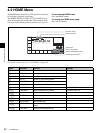
4-3 TC Menu
Chapter 4 Menu Settings
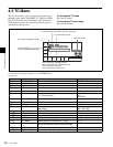
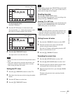
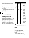
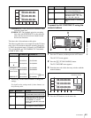
Selecting the time code and the user bits to be recorded
Use the [F6], [F7], and [F9] buttons in the TC menu to
specify the time code and the user bits to be recorded. The
specifications for the various button settings are shown in
the following table.
1) The DF/NDF setting on the [F9] button is applied to the time code only
when “prst” is specified by the [F7] button; the DF/NDF setting is always
applied for the CTL timer.
2) Specify the signal to be regenerated with the VTR SETUP menu item 608
“TCG/UBG REGENE MODE”. Signals not specified by this menu item
are automatically set to Preset mode, regardless of the [F7] button setting.
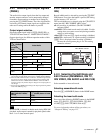
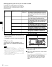
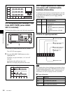
Setting time codes
To set time codes, select “prst” with the [F7] (TCG
MODE) button in the TC menu and then follow the steps
below.
• Set the [F8] (RUN MODE) button to “rec” before setting
the time data for recording. When you select “rec”, time
data advances from a set value only during recording.
When you select “free”, time code advances in real time
after the initial value has been set.
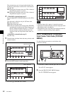
• During recording, VITC is always written to the AUX
data area of the video signal.
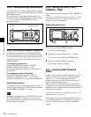
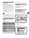
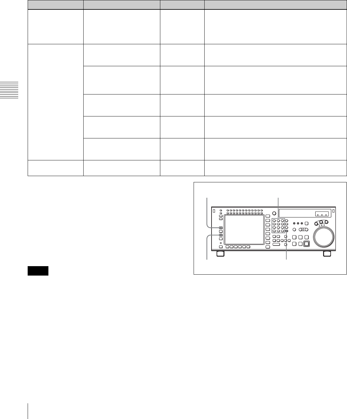
1
Press the [F1] (TIMER SEL) button to select the TC
(time code) to be set.
2
Enter the new setting in the data entry window with the
numeric buttons.
For example, to enter 01H00M30S00F, press 1, 0, 0, 3,
0, 0, 0. (The leading 0 is not required. When the
entered value is less than eight digits, the leading
digit(s) is (are) set to 0 when you press the SET
button.)
[F7] (TCG MODE) [F6] (REGENE SOURCE) [F9] (DF/NDF) Time code and user bits recorded
prst
DF/NDF/auto
1)
TC/UB enables TCG/UBG values to be recorded. Any
time code can be specified for the time code generator
and the user bits generator. The running mode for the
recorded time code data conforms to that specified by
the [F9] button.
regene
2)
int-L TC/UB enables TCG/UBG values to be recorded. The
time code generator and the user bits generator lock to
the time data recorded longitudinally on the tape.
int-V TC/UB enables TCG/UBG values to be recorded. The
time code generator and the user bits generator lock to
the time data recorded in the video signal AUX data
area on the tape.
ext-L TC/UB enables TCG/UBG values to be recorded. The
time code generator and the user bits generator lock to
the time data input from the TIME CODE IN connector.
SDI-V TC/UB enables TCG/UBG values to be recorded. TCG/
UBG values are controlled by VITC time data in the
video signal input to the HD SDI INPUT A/B connector.
SDI-L TC/UB enables TCG/UBG values to be recorded. TCG/
UBG values are controlled by LTC time data in the
video signal input to the HD SDI INPUT A/B connector.
auto “regene/int-L” is set in assemble or insert mode and
“prst” is set in other modes.
Notes
3
4
21