


25
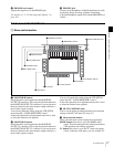
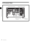
2-2 Connector Panel
Chapter 2 Locations and Functions of Parts
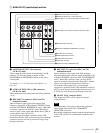
1 ANALOG I/O (input/output) section
a MONITOR OUTPUT L/R connectors
(XLR-3-31, male)
These output the audio signals for monitoring L and R
channels. To select the signals to output, use the
MONITOR R and MONITOR L buttons on the lower
control panel.
For details, see “5-1-2 Selecting Audio Signals” on
page 103.
b AUDIO OUTPUT CH1 to CH4 connectors
(XLR-3-31, male)
These output up to four analog audio signal lines (channels
1 to 4).
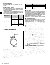
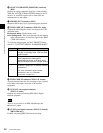
c REF. INPUT 1 connectors (BNC) and 75Ω
termination switch
Input a reference video signal of the selected field
frequency. Select HD or SD with the VTR SETUP menu
item 006 “EXTERNAL REFERENCE select”. When HD
is selected, input a tri-level SYNC signal. When SD is
selected, input a video signal with chroma burst (VBS) or
a monochrome video signal (VS).
A loop-through connection is possible. Set the 75Ω
termination switch to OFF if you are using a loop-through
connection and set it to ON if you are not using a loop-
through connection.
d REF. INPUT 2 connectors (BNC) and 75Ω
termination switch
Input a reference video signal of the field frequency
selected for the format converter output. Select HD or SD
with the VTR SETUP menu item A08 “FC REFERENCE
select”. When HD is selected, input a tri-level SYNC
signal for external synchronization. When SD is selected,
input a video signal with chroma burst (VBS) or a
monochrome video signal (VS). A loop-through
connection is possible. Set the 75Ω termination switch to
OFF if you are using a loop-through connection and set it
to ON if you are not using a loop-through connection.
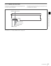
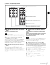
e SD OUT SYNC connector (BNC)
This outputs an NTSC or PAL signal for external
synchronization.
The output phase is the same as that of the composite
signal output from the SD OUT COMPOSITE
(MONITOR) connector.
Because the output phase changes with the operation mode
of the VTR, use this for synchronization with the video
monitor.
AUDIO OUTPUT
MONITOR OUTPUT
CUE
TIME CODE
ANALOG I/O
HD REF. OUT SD OUT
CH1
R L IN OUT
1
OFF ON
600
OFF ON
75 75
2 (OPTION)
OFF ON
OUT
1
2
SYNC
COMPOSITE
(MONITOR)
CH2 CH3 CH4
IN
REF. INPUT
1 MONITOR OUTPUT L/R connectors
2 AUDIO OUTPUT CH1 to CH4 connectors
3 REF. INPUT 1 connectors and 75Ω termination switch
4 REF. INPUT 2 connectors and 75Ω termination switch
5 SD OUT SYNC connector
6 SD OUT COMPOSITE (MONITOR) connector
7 HD REF. OUT connectors
8 TIME CODE OUT connector
9 TIME CODE IN connector
0 CUE OUT connector
qa CUE IN connector (SRW-5500 only)
Note