


16
2-1 Control Panel
Chapter 2 Locations and Functions of Parts
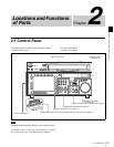
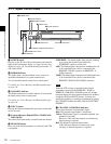
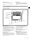
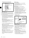
2-1-1 Upper Control Panel
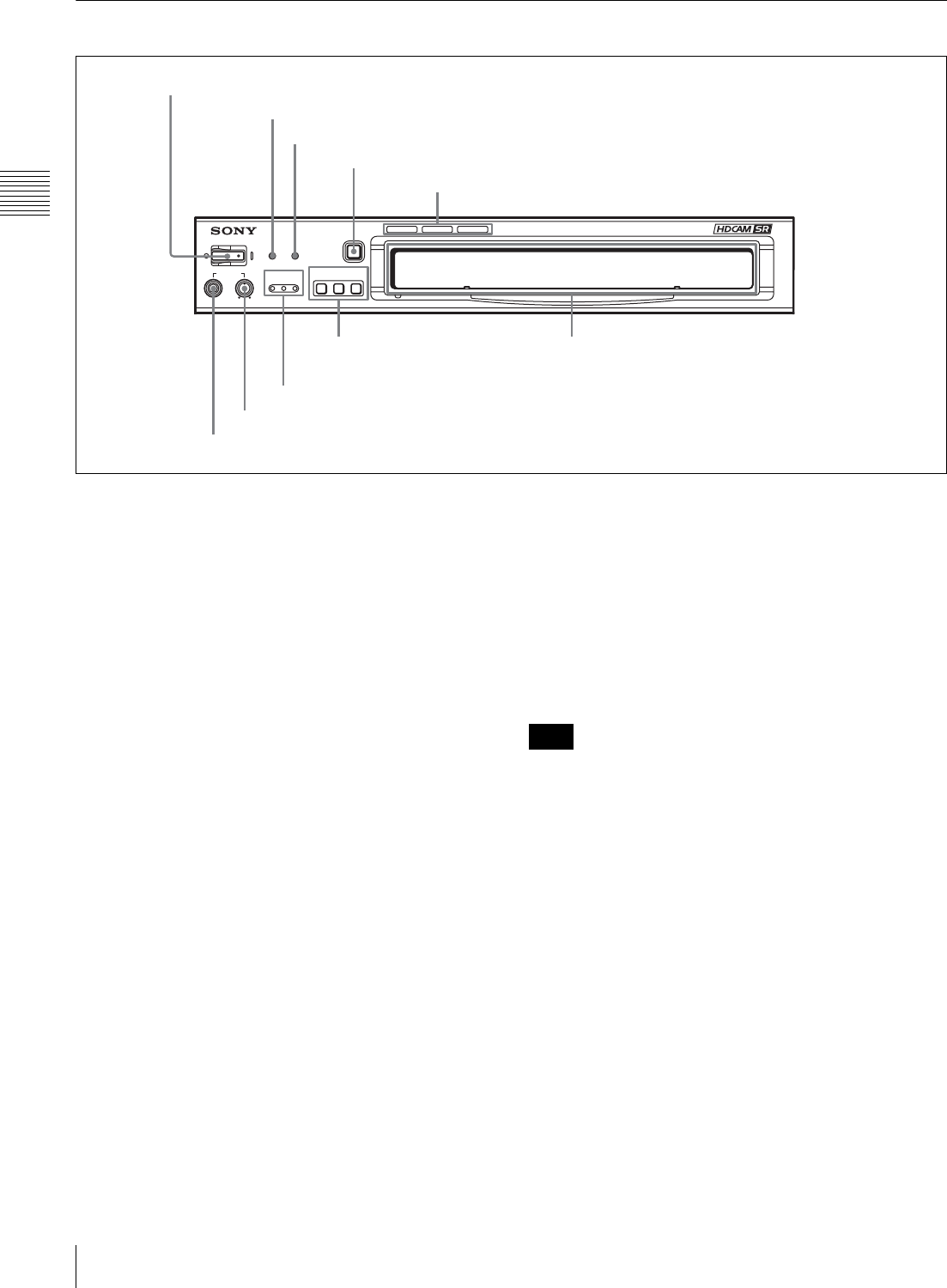
a POWER switch
Pressing on the ‘(’ side of this switch powers the unit and
lights up the information display (see page 20) and color
display (see page 18). To turn the unit off, press on the ‘a’
side of the switch.
b ERROR indicator
This lights when a serious problem occurs, such as an
operational malfunction or system internal error.
You can check the details on the lower control panel.
For details, see “Error Messages and Warning Messages”
on page 134.
c WARNING indicator
This flashes when there is a fault in the unit. You can check
the details on the lower control panel.
For details, see “Error Messages and Warning Messages”
on page 134.
d EJECT button
Pressing this button automatically ejects the cassette after
several seconds.
e Format indicators (Digital BETACAM/HDCAM/
HDCAM SR)
These show the format of the cassette loaded into the unit.
f REMOTE buttons
Press one of the following buttons, to select how the VTR
is controlled.
ETHERNET: This button lights when pressed, enabling
access from the network connected to the
ETHERNET connector on this unit.
1(9P): This button lights when pressed, enabling this unit
to be controlled from a device connected to the
REMOTE 1-IN(9P) connector or REMOTE 1-I/
O(9P) connector.
2(50P): This button lights when pressed, enabling this unit
to be controlled from a device connected to the
REMOTE 2 PARALLEL I/O(50P) connector.
When the VTR is being controlled by the external
equipment connected to the REMOTE 1-IN(9P) or
REMOTE 2 PARALLEL I/O(50P) connector, all tape
transport buttons and edit operation buttons are disabled,
except the STOP and EJECT buttons. You may also
specify the disabling or enabling of all buttons by setting
the VTR SETUP menu item 008 “LOCAL FUNCTION
ENABLE”.
g CHANNEL CONDITION indicators
These show the status of the playback signal.
Blue: The playback signal status is satisfactory.
Yellow: The playback signal is somewhat degraded, but
playback is possible.
However, if this indicator remains lit continuously,
head cleaning is required.
Red: The playback signal has deteriorated.
If this indicator remains lit continuously, head
cleaning or internal inspection is required.
SRW-5000
HD DIGITAL VIDEO CASSETTE RECORDER
EJECT
POWER
REMOTE
CHANNEL
CONDITION
PHONES
ERROR WARNING
ETHERNET
1(9P) 2(50P)
1 POWER switch
2 ERROR indicator
3 WARNING indicator
4 EJECT button
5 Format indicators
6 REMOTE buttons
7 CHANNEL CONDITION indicators
8 PHONES level control
9 PHONES jack
Cassette compartment
Note