


21
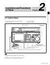
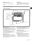
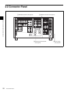
2-1 Control Panel
Chapter 2 Locations and Functions of Parts
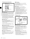
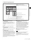
Page 2: System status
ACTIVE LINE: Shows the status of 1080/1035
conversion active line.
1080t1080
1080t1035(CROP)
1080t1035(CONV)
1035t1035
1035t1080(PANEL)
1035t1080(CONV): Shows the current conversion
status.
- - - - -: Cannot be converted.
OFF: No conversion done.
DOWN CONV. OUTPUT: Shows the output status of the
down converter.
ACTIVE: Output.
MUTING: No output.
EOS: Appears at the location of the time code for the valid
end of the previous recording.
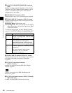
Page 3: Phase (OUTPUT)
HD SDI OUTPUT ADV.: Shows the phase of the main
line HD SDI output.
OFF: In phase with reference.
–90H: 90H (HD) advanced with respect to reference.
DOWN CONV. OUTPUT ADV.: Shows the phase of the
down converter output.
OFF: In phase with reference.
–2H: 2H (SD) advanced with respect to reference.
Page 4: Phase (AUDIO)
AUDIO PB OUTPUT ADV.: Shows the phase of the
audio output signal.
OFF: Output in phase with the video output signal.
–1Frame: Output one frame advanced with respect to
the video output signal.
AUDIO INPUT DELAY: Shows the recording phase of
the audio input signal.
OFF: Recorded in phase with the video output signal.
+1Frame: Recorded one frame delayed with respect to
the video input signal.
AES/EBU & ANA OUTPUT: Shows the phase of the
AES/EBU and ANALOG AUDIO outputs.
REF: Output in phase with reference.
FC: In phase with the FC output.
–90H(HD): 90H (HD) advanced with respect to
reference.
–2H(SD): 2H (SD) advanced with respect to
reference.
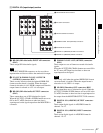
Page 5: Phase (TC)
TC INPUT DELAY: Shows the recording phase of the
input time code.
OFF: Recorded in phase with the input video signal.
+1Frame: Recorded one frame delayed with respect to
the input video signal.
LTC OUTPUT: Shows the phase of the output LTC.
LINE: Output in phase with the main line HD SDI
output.
FC: Output in phase with the FC output.
Page 6: Meta Data
The display changes depending on the tape format in use.
• HDCAM-SR
META DATA LINE(REC): Shows the status of the
three lines for metadata recording on this unit.
META DATA LINE(OUT): Shows the status of the
three lines of main HD SDI output into which
metadata is multiplexed.
META DATA LINE(FC): Shows the status of the three
lines of output from the optional HKSR-5001
format converter board into which metadata is
multiplexed.
META DATA LINE(SD): Shows the status of the three
lines of SD SDI output into which metadata is
multiplexed.
• HDCAM
Displays L1/L2/DID/SDID. This combination is
counted as 1 packet. Up to 3 packets can be recorded.
On the SRW-5500, the system settings related to
recording are shown on the left. If data is detected in the
input signal, the L1/L2 values are highlighted. The right
side shows playback values detected on the tape.
The ACTIVE LINE setting displayed on page 2 can be
made in the SYSTEM screen. The phase settings displayed
on pages 3 to 5 and the settings relating to META DATA
recording displayed on page 6 can be made in the PHASE
SET/META DATA menu under the ALT+OTHERS
CHECK menu in the MAINTENANCE menu.
For details, refer to the Installation Manual.
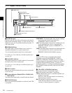
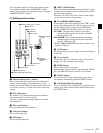
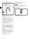
b REF SYNC (reference signal) indicators
These indicate the signal selected as the reference signal.
If there is no reference signal input to the selected
connector, the STOP button flashes.
EXT SD: Lights when “extern SD” is selected by the VTR
SETUP menu item 006 “EXTERNAL REFERENCE
select”.
EXT HD: Lights when “extern HD” is selected by the
VTR SETUP menu item 006 “EXTERNAL
REFERENCE select”.
INPUT VIDEO: Lights when “INPUT” is selected by the
VTR SETUP menu item 005 “SERVO/AV
REFERENCE select”.
c PREREAD indicator
Lights up during preread mode.
For more information about PREREAD, see “6-2-2
Animation Editing” on page 127.
Note