


33
3-2 Reference Signals
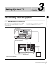
Chapter 3 Setting Up the VTR
3-2-2 Reference Signal Connections
Make the reference signal connections as follows,
according to your recording or playback requirements.
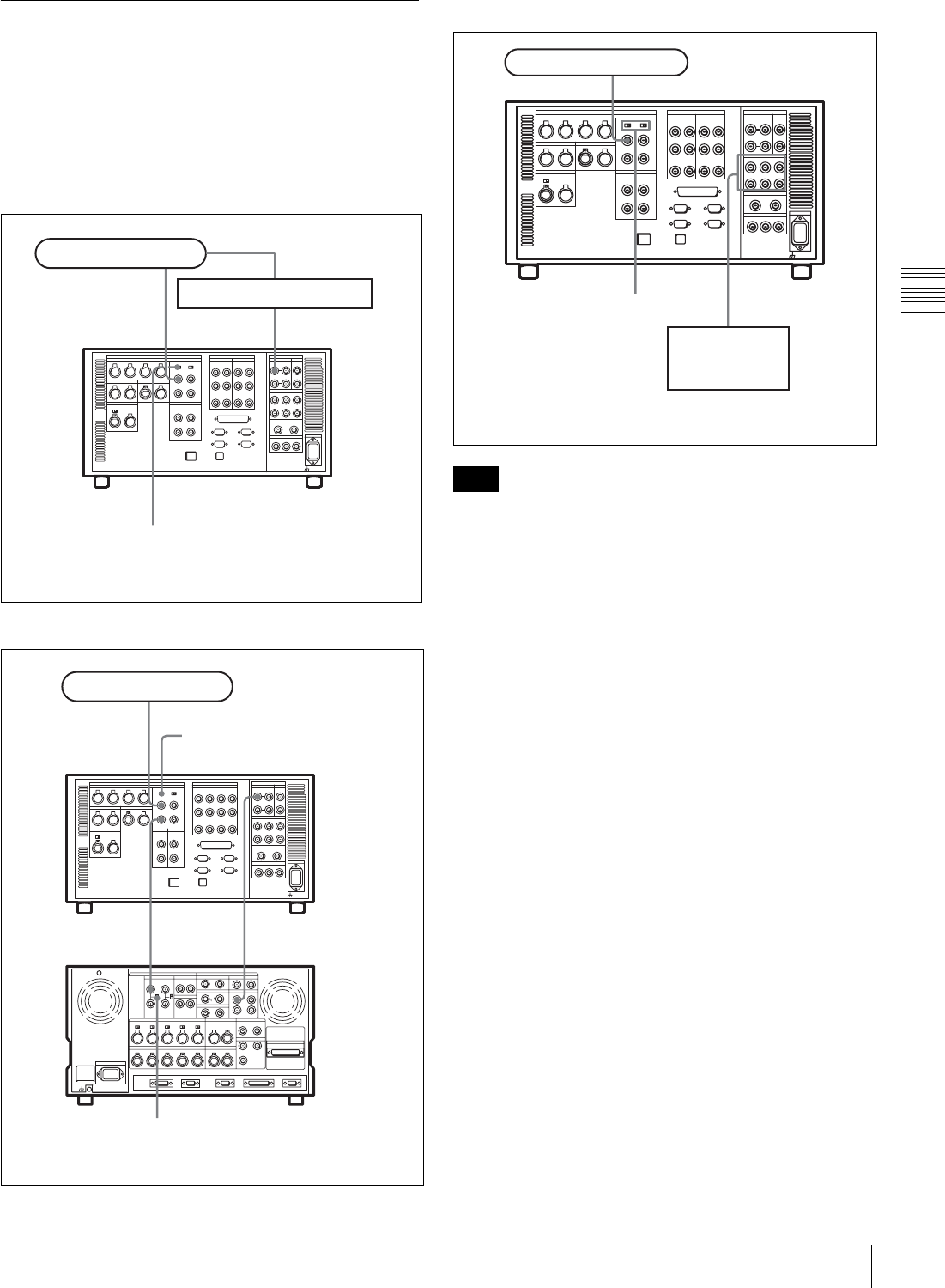
Reference signal connections
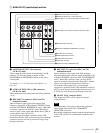
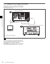
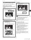
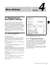
For recording signals from a switcher or signal
generator
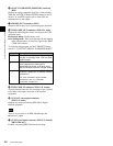
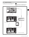
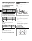
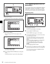
For recording signals from a HD VTR
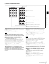
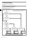
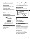
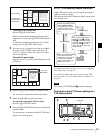
For playback
The following signals can be used as a reference signal.
• HD trilevel SYNC signal of an appropriate field
frequency for external synchronization
• Black burst signal of 525/59.94 Hz
• Black burst signal of 625/50 Hz
Input the signal of the appropriate field frequency for your
system.
Sync signals in 720p mode
Synchronize to an external sync signal when you want to
record or play back 720p signals on this unit (including
editing).
• When the 720/59.94p system is selected:
You can select the following reference signals from
menu item 006 “EXTERNAL REFERENCE select”.
extrn HD: 1080/59.94i tri-level SYNC signal
extrn SD: 525 black burst signal
• When the 720/50p system is selected:
You can select the following reference signals from
menu item 006 “EXTERNAL REFERENCE select”.
extrn HD: 1080/50i tri-level SYNC signal
extrn SD: 625 black burst signal
When you have directly connected the input and output
connectors of two SRW-5000/5500 units, you can also
perform dubbing with the VTR SETUP menu item 005
being set to “input”.
HD SDI INPUTREF. INPUT 1
Reference signal
Switcher or signal generator
SRW-5000/5500
a)
75Ω termination switch: ON
a) The figure shows the SRW-5500.
HD SDI OUTPUTHD SDI INPUT
HD SDI INPUT AREF. INPUT 1
REF. INPUT 1
Reference signal
SRW-5000/5500 (Recorder)
a)
75Ω termination switch: OFF
HDW-F500 (Player)
75Ω termination switch: ON
a) The figure shows the SRW-5500.
Note
HD SDI OUTPUT
REF. INPUT 1
Reference signal
HD serial input
monitor
SRW-5000/5500
a)
75Ω termination switch: ON
a) The figure shows the SRW-5500.