


32
Connections and Settings
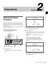
Chapter 2 Preparations
For details about the settings of the HDW-M2000/
M2000P, refer to the operation manual for the unit.
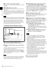
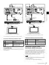
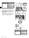
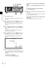
When using the editing functions of the
recorder (connections using the REMOTE
(9P) connector)
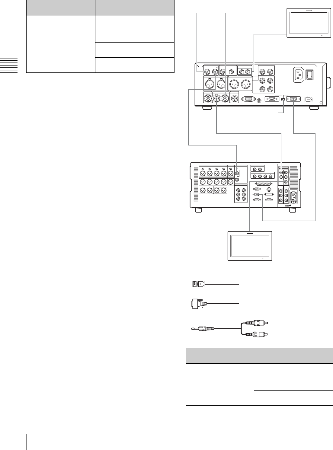
The following figure shows a cut editing system
comprising this unit as a player and an HDW-M2000/
M2000P unit as a recorder. In this example, video and
audio signals are connected by SDI, and control signals are
transferred via the REMOTE(9P) connector.
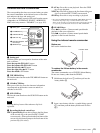
HDW-M2000/M2000P
(recorder) settings
This unit (player) settings
REMOTE 1(9P) button: Lit Set the setup menu item
INTERFACE SELECT
>REMOTE I/F to “9PIN/RS-
232C” (see page 103).
Remote control switch:
REMOTE
Remote connector selector
switch: REMOTE(9P)
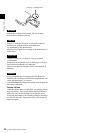
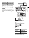
HDW-M2000/M2000P
(recorder) settings
This unit (player) settings
REMOTE 1(9P) button:
Unlit
Set the setup menu item
INTERFACE SELECT
>REMOTE I/F to “9PIN/RS-
232C” (see page 103).
Remote control switch:
REMOTE
75Ω
SDSDI OUTPUTHDSDI INPUT
AUDIO INPUT
HDSDI OUTPUT
12
REF VIDEO INPUT
TIME CODE
POWER
ANALOG HD INPUT
DIGITAL
AUDIO
(AES/EBU)
COMPOSITE OUTPUT AUDIO MONITOR
1/3 2/4
AUDIO OUTPUT
1/3 2/4
R L IN OUT
Y/G P
B /R
SYNS
RS232C REMOTE(9P)
PB /B
1/2
INPUT
OUTPUT
CONTROL
3/4
1/2 3/4
S400
MONITOR
-AC IN
HDSDI
OUTPUT
REMOTE 1-OUT(9P)
HDSDI
OUTPUT 3
(SUPER)
REMOTE(9P)
REF VIDEO
INPUT
REF VIDEO
INPUT
REF VIDEO
INPUT
HDSDI
INPUT
HDSDI
OUTPUT
AUDIO
MONITOR
HD video monitor
To analog audio input
connector
To HDSDI input connector
Reference
video signal
PDW-F75
(this unit, player)
HDW-M2000/M2000P
(recorder)
HD video monitor
To HDSDI input connector
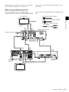
1: 75Ω coaxial cable (not supplied)
2: 9-pin remote control cable (not supplied)
3: Phono plug – stereo miniplug cable (not supplied)
2
1
1
3
Remote connector
selector switch
1
1
1