


23
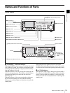
Names and Functions of Parts
Chapter 1 Overview
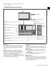
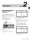
3 Digital signal input/output section
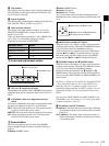
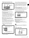
a HDSDI (HD serial digital interface) INPUT
connector (BNC type)
This inputs HD format video and audio signals.
b HDSDI (HD serial digital interface) OUTPUT
connectors (BNC type)
These output HD format video and audio signals.
When CHAR SEL on page P1 of the function menu is set
to “ON”, and DISPLAY CONTROL >HD CHARA in the
setup menu is set to “ALL” (or either “HDSDI2” or “ALL”
for the HDSDI OUTPUT 2 connector), information such
as timecode, menu settings, and error messages is
superimposed on the output signals (see page 40).
c SDSDI OUTPUT connector (BNC type)
This outputs SDSDI signals downconverted from HD
video input signals, or the SDSDI signals being played
back or being recorded.
When CHAR SEL on page P1 of the function menu is set
to “ON”, and DISPLAY CONTROL >SD CHARA in the
setup menu is set to “SDI” or “ALL”, information such as
timecode, menu settings, and error messages is
superimposed on the output signals (see page 40).
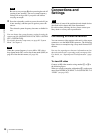
4 Digital audio signal input/output
section
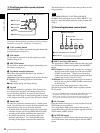
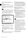
a DIGITAL AUDIO (AES/EBU) INPUT 1/2 and 3/4
connectors (BNC type)
These input AES/EBU format digital audio signals. The
1/2 connector corresponds to audio channels 1 and 2, and
the 3/4 connector corresponds to audio channels 3 and 4.
To handle input signals as non-audio data, use the AUDIO
CONTROL >DATA MODE item of the setup menu (see
page 102) to set the input of channels 1 and 2 (CH1/CH2
IN) or the input of channels 3 and 4 (CH3/CH4 IN) to
“DATA”.
b DIGITAL AUDIO (AES/EBU) OUTPUT 1/2 and
3/4 connectors (BNC type)
These output AES/EBU format digital audio signals. The
1/2 connector corresponds to audio channels 1 and 2, and
the 3/4 connector corresponds to audio channels 3 and 4.
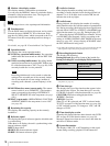
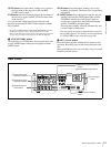
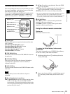
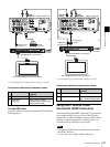
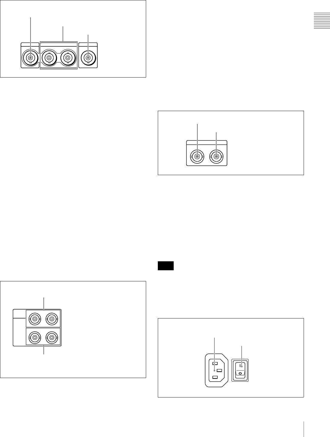
5 Timecode input/output section
a TIME CODE IN connector
Inputs SMPTE timecode generated by an external device.
b TIME CODE OUT connector
Outputs the following timecode, depending on the
operating state of the unit.
During playback: Playback timecode
During recording: The timecode from the internal
timecode generator or the timecode input to the TIME
CODE IN connector.
In E-E mode no timecode is output if TIME CODE >EE
OUT PHASE in the setup menu is set to “MUTING” (see
page 98).
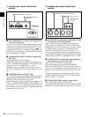
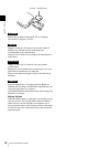
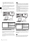
6 Power supply section
HDSDI INPUT
HDSDI OUTPUT
12
SDSDI OUTPUT
1 HDSDI INPUT connector
2 HDSDI OUTPUT connectors
3 SDSDI OUTPUT
connector
DIGITAL
AUDIO
(AES/EBU)
1/2
INPUT
OUTPUT
3/4
1/2 3/4
1 DIGITAL AUDIO (AES/EBU) INPUT
1/2 and 3/4 connectors
2 DIGITAL AUDIO (AES/EBU) OUTPUT
1/2 and 3/4 connectors
Note
TIME CODE
IN OUT
1 TIME CODE IN connector
2 TIME CODE OUT connector
POWER
-AC IN
1 - AC IN connector
2 POWER switch