


49
DAB1 DISTRIBUTED AUDIO SYSTEM
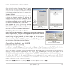
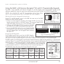
Using the DAB1 with Sonance Navigator
®
K2 and K1 Programmable Keypads
The DAB1 is also compatible with Sonance Navigator K1 and K2 keypads. These programmable keypads provide
additional capability for zones that require more sophisticated control than the DAB1 and C4630 SE keypads offer.
NOTE: For detailed K1 and K2 programming instructions please
refer to the documentation that is available for those keypads.
Wiring K2 and K1 Keypad Connections
Sonance K1 and K2 keypads connect to the DAB1 the same way as the DAB1
Keypad and C4630 SE Main Keypad:
1. In direct runs from keypad to controller, pull a length of CAT5 wire from every
keypad mounting location to the DAB1 location. The maximum length of any
single CAT5 cable connecting a K1 or K2 to the DAB1 is 250’.
2. Terminate each CAT5 cable with RJ45 connectors on the DAB1
end. Follow the TIA 568B wiring standard (see
Figure 69
).
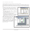
3. Connect the CAT5/RJ45 cable to the zone’s Keypad Controller
Port on the DAB1 and to the multi-pin connector on the back of
the K1/K2 keypad (don’t use the keypad’s RJ45 connector).
See
Figure 70
.
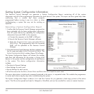
Powering K2 Keypads
The K2 keypad requires more current than the DAB1 Keypad or
C4630 SE Main/Numeric Keypad combination does. You need to
take special care when using these keypads to ensure there is adequate current to properly run all connected keypads.
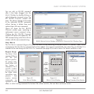
The DAB1 supplies 1A of total keypad current through its keypad connections. When the rear-panel Z
ONE 4 – 6 KEYPAD POWER
switch (see
Figure 71
) is in the INT (internal) position this current is evenly divided between all six Zone Keypad Connections.
When the switch is in the EXT (external) position, the DAB1 supplies all 1A of current to Zones
1 – 3, while Zones 4 – 6 must be powered by an external PS2 power supply (available sep-
arately) connected to the Z
ONE 4 – 6 KEYPAD EXTERNAL POWER Connection (see
Figure 71
).
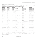
The table below shows how many of each type of keypad can be used:
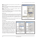
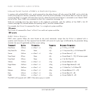
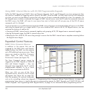
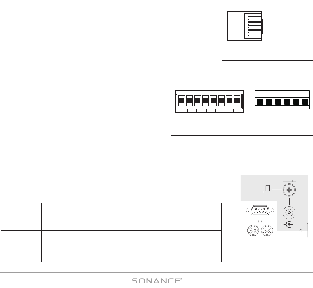
RJ45 Connector
(Flat Side UP)
TIA 56
8
B
Wiring Standard
PIN
1
2
3
4
5
6
7
8
COLOR
White/Orange
Orange
White/Green
Blue
White/Blue
Green
White/Brown
Brown
SIGNAL
No Signal
No Signal
No Signal
IR Data
Status
No Signal
Ground
+12V DC
Figure 69:
Keypad Connection RJ45 Pinout
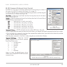
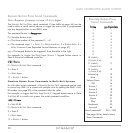
PIN #5
PIN #4
PIN #7
PIN #8
PIN #4
PIN #5
PIN #7
PIN #8
K2 CONNECTOR K1 CONNECTOR
Figure 70: K1/K2 Keypad Wiring
F1AL 12VDC
RS-232
12 VDC
1.0 A IN
ZONE 4-6
KEYPAD POWER
INT
EXT
–
+
F
1AL 12VD
C
12 VDC
1.
0
A I
N
Z
ONE 4-
6
K
EYPAD P
O
WER
INT
EXT
–
+
Figure 71:
Keypad External Power
Connection
Z
ONE
4 – 6 K
EYPAD
I
NTERNAL
P
OWER
Switch Position
INT (Internal)
Supplies 1A Total
Up to
6 Sets
Up to
12 Sets
Up to
12
Up to
24
Up to
6
Up to
12
Up to
3
Up to
7
EXT (External, w/PS2
Power Supply)
Supplies 2A Total
C4630 SE
Main/Numeric Keypads
Max LED Brightness,
(Each Set Draws 165mA)
K1 Keypads
Backlight ON,
(Each Draws
70mA)
Up to
12
Up to
24
DAB1 Keypads
Max LED
Brightness,
(Each Draws
52mA)
K2 Keypads
Med LED
Brightness,
(Each Draws
150mA)
K2 Keypads
Max LED
Brightness,
(Each Draws
265mA)