


19
DAB1 DISTRIBUTED AUDIO SYSTEM
with the Sonance Control Manager software. The Sonance Control Manager can also be used to change the out-of-the-box
button functions.
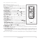
C4630 SE Numeric Keypad (see Figure 15, opposite)
The C4630 SE Numeric Keypad incorporates ten numeric buttons labeled “0” through “9”, and two buttons labeled “+”
and “–”. Like the C4630 SE Main Keypad, each of these buttons has P
RESS, PRESS-AND-HOLD and DOUBLE-PRESS functions.
Unlike the C4630 SE Main Keypad, the Numeric Keypad has no “out-of-the-box” functions — it must first be programmed
with the Sonance Control Manager software. The Numeric Keypad con-
nects to the Main Keypad with the included 14-pin ribbon cable; it can-
not operate on its own. See
Mounting the C4630 SE Keypads
, on page
20 for details.
C4630 SE Main Keypad IR Receiver Holster
The C4630 SE Main Keypad does not feature a built-in IR receiver: it
has a holster that accepts a Sonance FSMR1 Full-Spectrum IR Receiver
(part #92222) or MR1 Micro IR Receiver (part #91344), both available
separately. A window on the front of the keypad allows the IR receiver
to function (see
Figure 15, opposite
). IR talkback is through the
keypad’s Z
ONE OFF button.
If the Main Keypad is mounted in a location that creates interference from
sunlight when the IR receiver is installed in its holster, you can move the
IR receiver to another location in the room and still wire it to the keypad.
NOTE: When using C4630 SE keypads, IR receivers must be
connected to the keypads to allow the included IR remote to control
the DAB1 from inside the listening zones, and to allow source com-
ponent remotes to control their respective source components from
inside the listening zones.
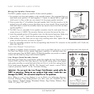
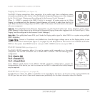
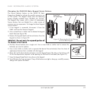
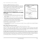
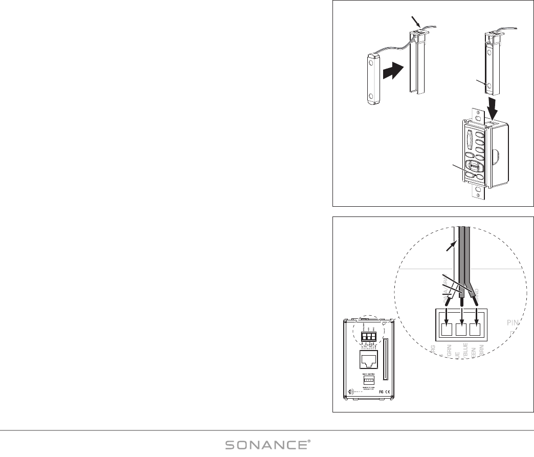
Installing an IR receiver Into a C4630 SE Main Keypad:
1. Insert the IR receiver into the keypad holster as shown in
Figure 16A
.
Feed the ribbon cable through the opening in the holster.
2. Carefully insert the holster into the keypad as shown in
Figure 16B
. The IR
receiver’s photodiode should be directly behind the keypad’s IR window.
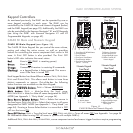
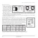
3. Connect the IR receiver’s 3-conductor ribbon cable to the keypad’s rear-
panel IR R
ECEIVER CONNECTION as shown in
Figure 17
. The connection
features a 3-pin removable connector similar to the ones used for the
speaker connectors. Insert the wires into the openings at the rear of the
connector and secure them by tightening the screws at the top of the
connector.
• The gray wire on the ribbon cable is the D
ATA wire, the center wire is
+12V and the remaining wire is G
ROUND.
FSMR1/MR1
IR Receiver
IR Receiver
Holster
Feed Ribbon Cable
through Opening
Insert Holster
into Main Keypad
IR
Photodiode
IR
Window
A. B.
Figure 16:
IR Receiver Holster
C4630
MAIN
KEYPAD
RESERVED FOR NUMBERIC KEYPAD
PIN 14
PIN 1
•
1 2
IR DATA (white)
+12V (center)
GROUND
FROM IR
RECEIVER
Figure 17:
Connecting the IR Receiver
to the Keypad