16
DAB1 DISTRIBUTED AUDIO SYSTEM
55.. CC
OOMMMMOONN
IIRR OO
UUTT
PPoorrttss::
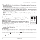
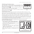
Four 3.5mm mini jacks that output all IR commands regardless of zone for all source compo-
nents (all zones have control of all sources). Intended for all systems except those that contain multiple same-brand,
same-model source components.
• Connect one Sonance OptiLinQ-type IR emitter to each C
OMMON IR Out port for each common source component
to be controlled. Attach one emitter to the IR window on each source component.
66.. LL
OOCCAALL
IIRR OO
UUTT
PPoorrttss::
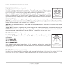
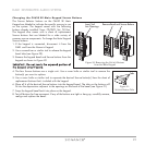
Six 3.5mm mini jacks (one for each zone) that allow control of a specific source component from
a specific zone. Connect one Sonance OptiLinQ-type emitter to the appropriate L
OCAL IR OUT jack and attach the
emitter to the source component’s IR window.
EExxaammppllee::
The living room is Zone 1. The CD changer is Source 2 and is to be controlled
only
from the living room.
Connect the IR emitter to the Zone 1 L
OCAL IR OUT jack and attach it to the IR window on the CD changer.
The CD changer can be controlled only from the living room, but all zones can still select Source 2 and listen to the CD
changer when it is playing.
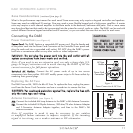
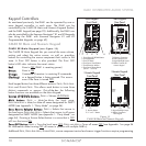
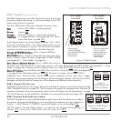
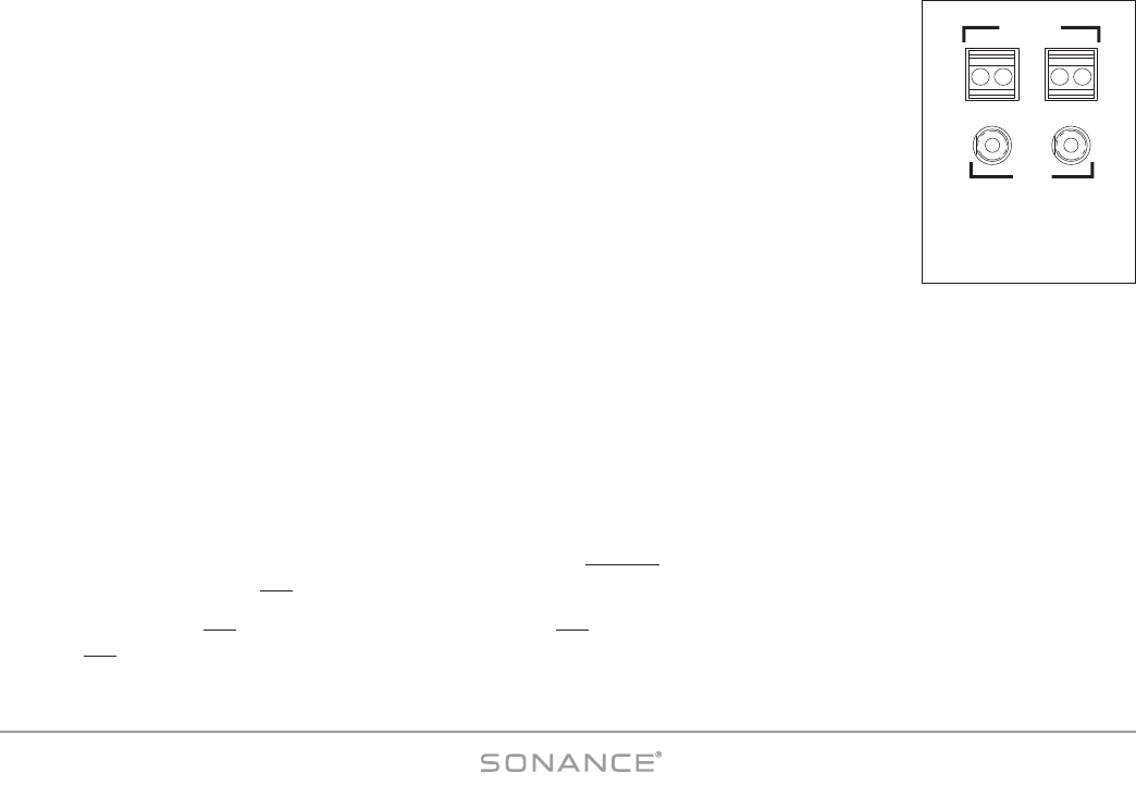
Control Output, Control Input and Sync Connections (see Figure 12)
CONTROL OUT Terminal
One 2-wire screw connector that outputs 12VDC @ 100mA when at least one DAB1 zone is
active. Turns OFF (0VDC) when all zones are OFF. Can be used for triggering external devices
such as a zone-specific external amplifier. Accepts one pair 14 – 24 AWG wire.
C
ONTROL INPUT
Terminal
A general trigger input that can be used for Paging or sense input as part of a DAB1 S
TATUS
test in a macro. Requires 5 – 24V AC or DC @ 100mA. Accepts one pair 14 – 24AWG wire.
Wiring the C
ONTROL Connections
1. Strip approximately ¼" of insulation from each conductor and twist the strands until tight
to prevent stray strands.
2. Be sure to maintain proper polarity by connecting the appropriate ‘+V’ and ‘GND’ terminals on the device to the
appropriate ‘+V’ and ‘GND’ terminals on the DAB1. Be sure the connections are tight and that there are no frayed ends
sticking out that could cause a short-circuit.
S
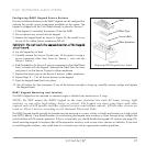
YNC Connections
Two 3.5mm mini jacks that are used to trigger-link up to four DAB1s to provide communication between multiple DAB1
units that form large systems with more than 6 zones. For details, see
Appendix 1: Party Mode
, on page 54. Use mono
3.5mm mini cables to daisy-chain the S
YNC jacks of all DAB1 units in the system.
Audio and IR will pass-through multiple DAB1s that are in the Standby mode. Power for the source components should be
managed separately or left ON
.
If no other zones are ON and a zone on a DAB1 is turned ON with a Source button PRESS, only that DAB1 and that zone
will turn ON
.
+ OUT - INPUT
12 VDC @
100 mA
+6 -24
AC/DC
CONTROL
SYNC
Figure 12:
Control Input/ Output
and Sync Connections


