


15
DAB1 DISTRIBUTED AUDIO SYSTEM
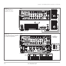
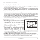
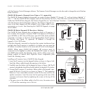
Connecting a High-Power Amplifier in a Zone
1. Set the zone’s Variable/Fixed Output switch to the VARIABLE (OUT) position. Note: If the Zone LINE OUTPUT is set to FIXED,
audio will continuously pass to the amplifier inputs, defeating any signal-sensing auto-ON/OFF triggering. In this case,
the amplifier should be triggered by a control voltage or other means.
2. Connect a stereo RCA cable from the appropriate Zone Line Outputs on the DAB1 to the high-power amplifier’s input
connectors (see
Figure 9
, opposite). The V
ARIABLE setting allows the zone’s volume to be controlled by the DAB1 via a
keypad or a properly-programmed IR remote.
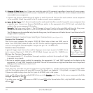
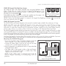
Using a Multi-Channel Amplifier for Sub-Zone Expansion
1. Set the zone’s Variable/Fixed Output switch to the F
IXED (IN) position.
2. Connect a stereo RCA cable from the appropriate Zone Line Outputs on the DAB1 to the multi-channel amplifier’s Bus
input connectors (see
Figure 10
, opposite). For example, an 8-channel amplifier like the Sonamp 875D SE will let
you put four speaker pairs in the zone. The V
ARIABLE output setting allows the DAB1’s Mute function to mute all four
sub-zones. Volume for each pair of speakers in each sub-zone is controlled by an in-wall volume control.
3. Connect the Control Out on the DAB1 to the External Control input on the sub-zone amplifier (if available) to
automatically power-up the external amp when any zone on the DAB1 is ON.
Note: The DAB1 can also turn connected amplifiers ON and OFF via serial control. See page 43.
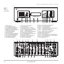
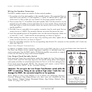
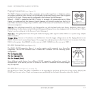
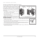
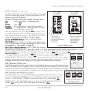
IR Connections (see Figure 11)
11.. IIRR LL
IINNKK
PPoorrtt::
3.5mm mini jack that creates an IR buss for Common IR
signals when using multiple DAB1s in a system.
• When using two DAB1s, use a 3.5mm mono mini cable to connect
the IR Link jacks on the two units.
• When using three or more DAB1 Controllers, use mini plug
Y-adapters on the IR Link jack on the primary DAB1 to connect to
the IR Link jacks of the secondary DAB1s.
22.. PP
RROOGGRRAAMMMMEEDD
IIRR OO
UUTT
PPoorrttss::
Four 3.5mm mini jacks that
output IR commands to the four individual source components as
configured in the Sonance Control Manager. (The default
Programmed IR Port settings correspond to the Input Source
numbering: Port 1 = Source 1, etc.) Allows IR signals to be routed to
specific source components, for selective control of multiple same-brand, same-model components.
• Connect one Sonance OptiLinQ
®
-type IR emitter to each Programmed IR Out port for each source component to be
controlled. Attach one emitter to the IR window on each source component.
33.. ZZ
OONNEE
IIRR DD
AATTAA
LLEEDD::
Six amber LEDs (one for each zone) that flash to indicate IR activity in their respective zones.
44.. FF
RROONNTT
IIRR PP
AASSSS
SSwwiittcchh::
Passes IR commands from 3rd-party remotes through the front-panel IR receiver to the
Programmed and/or Common IR Outputs, as configured in the Sonance Control Manager software.
1
456
23
Figure 11: IR Connections