


13
DAB1 DISTRIBUTED AUDIO SYSTEM
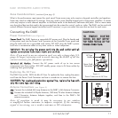
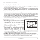
Wiring the Speaker Connectors
The DAB1’s speaker outputs are rated for 8-ohm nominal speakers.
1. Run speaker wire from each speaker to the controller location. We recommend that you
mark each wire’s positive (‘+’) and negative (‘–’) leads, its channel (left or right) and
which zone it is from so that you can connect it to the proper speaker terminals.
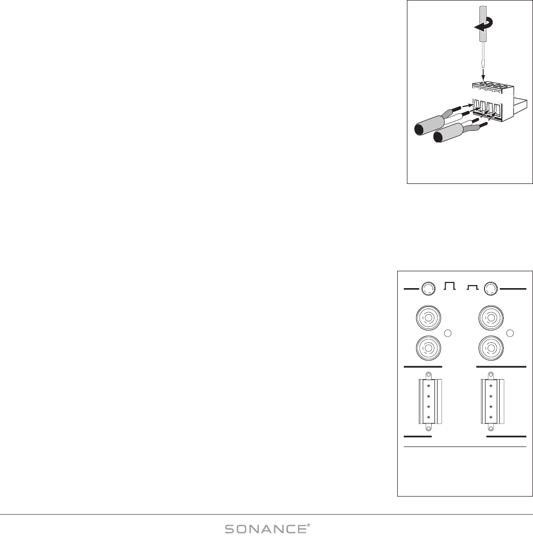
2. Strip no more than ¼” of insulation from each speaker lead. Twist the strands or tin the
exposed wire with solder to ensure that there are no stray strands. (Stray strands that
touch each other or touch the controller chassis can cause a short-circuit that can dam-
age the amplifier.)
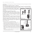
3. The DAB1 has six removable 4-wire speaker connectors (one for each zone) that can
accept wire up to 14AWG. The connector features set screws that secure the wires.
4. Insert the exposed portions of the speaker wires into the terminal openings. Make sure
to insert the ‘+’ and ‘–’ leads into the correct openings, as shown in
Figure 6
.
5. After making sure that there are no stray wires touching each other, tighten the set
screws to secure the wires, as shown in
Figure 7
.
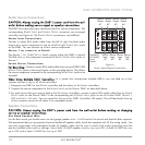
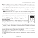
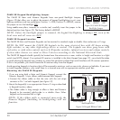
6. Press the removable connector into the corresponding zone S
PEAKER O
UT connector on the controller until it locks into
place (see
Figure 8
).
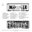
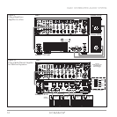
Zone Line Output Connections
In addition to Speaker Output connectors, each zone on the DAB1 also has a set of Line Output jacks (see
Figure 8)
.
The Zone Line Outputs let you connect high-power amplifiers to individual zones that
require more power than the DAB1’s built-in 30 Watt/ch amplifier can provide, or expand
a zone into sub-zones by using a multi-channel amplifier.
Line Output Fixed/Variable Switch
Each zone Line Output has a push-button switch that toggles the Line Output between
V
ARIABLE (OUT) and FIXED (IN). (See
Figure 8
.) The VARIABLE setting allows zone keypad
and remote controllers to control the level of the L
INE OUTPUTS. In the FIXED setting the LINE
OUTPUT level cannot be varied.
NOTE: The keypad and remote control M
UTE
controls function ONLY in the V
ARIABLE
setting.
II
MMPPOORRTTAANNTT
:: DDoo nnoott ppuusshh tthhee LLiinnee OOuuttppuutt FF
IIXXEEDD
//VV
AARRIIAABBLLEE
sswwiittcchh wwhhiillee tthhee
DDAABB11 iiss ooppeerraattiinngg.. DDooiinngg ssoo ccaann pprroodduuccee hhiigghh oouuttppuutt lleevveellss tthhaatt ccaann
ddaammaaggee tthhee DDAABB11,
, tthhee ccoonnnneecctteedd aammpplliiffiieerr oorr tthhee ssppeeaakkeerrss..
Note: When a zone’s Line Output is set to F
IXED
, the following Sonance
Control Manager Zone Setup features for that zone are disabled for the
Line Output: Default Volume, Maximum Volume, Page Volume, Balance, Bass,
Treble. See pages 32 and 33.
VARIABLE FIXED
OUT
IN
L
R
L
R
LINE OUT
SPEAKER OUT
8 Ω NOMINAL IMPEDANCE
34
L+
L-
R-
R+
L+
L-
R-
R+
Figure 8:
Zone Line Outputs, Speaker
Outputs and Line Output
Fixed/Variable Switches
L
+
L
–
R
–
R
+
Use
Screwdriver
to Tighten
Set Screws
Figure 7:
Wiring the Removable
Speaker Connectors