


84
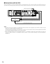
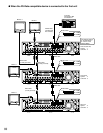
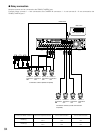
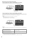
● Daisy connection
Multiple cameras can be connected to the RS485 (CAMERA) port.
Example: When cameras 1 - 4 are connected to the CAMERA IN connectors 1 - 4 and cameras 9 - 12 are connected to the
RS485 (CAMERA) port 1.
RS485 cable
Mode switch
Nos. 1,2,3,4,5,6 : ON
1
18
2
IN
OUT
CASCADE
OUT
16
16
3
15
15
14
14
13
2
1
13
12
12
11
11
10
10
9
9
8
8
7
7
6
6
5
5
4
4
3
3
2
2
1
1
VIDEO
AUDIO IN AUDIO OUT
MONITOR OUT CASCADE IN
MONITOR (VGA) ALARM/CONTROL
SERIAL ALARM
POWER
COPY 1
MODE
EXT STORAGE10/100BASE-TRS485(CAMERA)
DATA
AC IN
SIGNAL GND
1
4 2
612345
ON
Unit No. 10
Termination:
OFF
Unit No. 11
Termination:
OFF
Unit No. 12
Termination:
ON
Unit No. 9
Termination:
OFF
Unit No. 2
Termination:
OFF
Unit No. 3
Termination:
OFF
Unit No. 4
Termination:
ON
Unit No. 1
Termination:
OFF
78
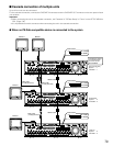
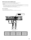
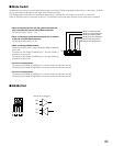
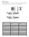
Combination cameras (RS485 compatible)
Combination cameras (coaxial communication
compatible)
Connect the RS485 camera to Switches required to be set 4-wire communication 2-wire communication
RS485 (1)
RS485 (2)
No.2
No.3
No.5
No.6
OFF
OFF
OFF
OFF
ON
ON
ON
ON