


73
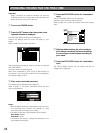
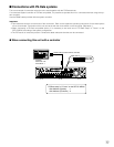
■ Connections when the unit is used independently
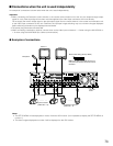
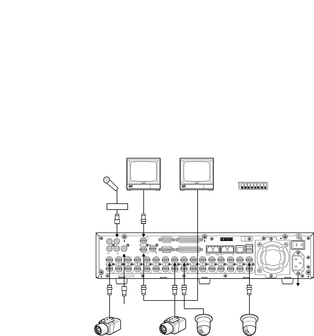
An example of connections is shown below when the unit is used independently.
Important:
• When connecting the Panasonic matrix switcher or the coaxial communication unit to this unit, the looped through output
signal for every video input signal from them must be supplied to the video input connectors of this unit directly.
Do not supply the monitor output signal or the spot output signal from the matrix switcher or the coaxial communication unit
to the video input connectors of this unit. Otherwise, the improper image switching may occur and the images displayed
before switching channels may be displayed and recorded.
• The power plug should be connected last.
• When connecting combination cameras, connect them to the video input connectors 1 - 8 when using the WJ-HD316A or
1 - 6 when using the WJ-HD309A (for coaxial communication).
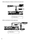
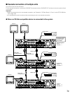
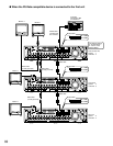
● Examples of connections
Notes:
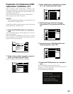
• The SETUP MENU will be displayed on monitor 2 and the VGA monitor. (It is impossible to display the SETUP MENU on
monitor 1.)
• The same images displayed on monitor 2 will be displayed on the VGA monitor.
Microphone
Note: If the DATA and RS485 ports are not
used, the mode switches should be used as
illustrated.
1
18
2
IN
OUT
CASCADE
OUT
16
16
3
15
15
14
14
13
2
1
13
12
12
11
11
10
10
9
9
8
8
7
7
6
6
5
5
4
4
3
3
2
2
1
1
VIDEO
AUDIO IN AUDIO OUT
MONITOR OUT CASCADE IN
MONITOR (VGA) ALARM/CONTROL
SERIAL ALARM
POWER
COPY 1
MODE
EXT STORAGE10/100BASE-TRS485(CAMERA)
DATA
AC IN
SIGNAL GND
1
4 2
System cameras
(VIDEO IN 9 - 16)
Combination cameras
(VIDEO IN 1 - 8)
For Audio Amplifier
Monitor 1
Monitor 2
120 V AC
60 Hz
• • • • • • • • • • • •
67812345
ON
Mode switch setting (Factory default)
Amplifier