


64
System controller
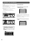
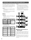
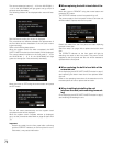
OPERATION OF THE UNIT IN THE CASCADE CONNECTION
When connecting multiple units (up to 4 units) in the cas-
cade connection, it is possible to monitor images from all
of the WJ-HD316A/309A in the cascade connection using
a monitor. It is necessary in advance to perform the set-
tings to operate the unit in the cascade connection. Refer
to a system administrator for further information.
Important:
• Video output signal will not be supplied from the MONI-
TOR (VGA) connector when connecting the units in the
cascade connection.
• When audio input signals are supplied to the AUDIO IN
connectors, audio will be heard from the respective
unit to the AUDIO IN connector.
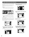
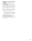
■ Setup
For the unit
• Select "ON" for "Cascade" of "PS.Data Setup" on the
SETUP MENU (Advanced) ("Comm" - PS.data Setup" -
"Cascade").
• Set the unit address as follows.
System Controller
System Controller
PS·Data compatible
system controller
(Unit Address: 001)
Monitor 2
ALARM
TIMER
HDD 2
ERROR
HDD 1
ALARM
SUSPEND
ALARM
RESET
OPERATE
MONITOR1
MONITOR2
1
5
9
13
2
6
10/0
14
3
7
11
15
4
8
12
16
SEQSHIFT OSD
PAN /
TILT
STOP
PLAY PAUSE
REC
-
REC STOP
ZOOM/
FOCUS
TEXT
COPY
DISK SELECT
EL-ZOOM
MARK
LOGOUT
IRIS
PRESET
/AUTO
A-B
REPEAT
GOTO
LAST
LISTED
SEARCH
BUSY
SETUP
/ESC
SET
REV
– +
FWD
PULL
Digital Disk Recorder
WJ-HD A
PAN/TILT
SLOW
ALARM
TIMER
HDD 2
ERROR
HDD 1
ALARM
SUSPEND
ALARM
RESET
OPERATE
MONITOR1
MONITOR2
1
5
9
13
2
6
10/0
14
3
7
11
15
4
8
12
16
SEQSHIFT OSD
PAN /
TILT
STOP
PLAY PAUSE
REC
-
REC STOP
ZOOM/
FOCUS
TEXT
COPY
DISK SELECT
EL-ZOOM
MARK
LOGOUT
IRIS
PRESET
/AUTO
A-B
REPEAT
GOTO
LAST
LISTED
SEARCH
BUSY
SETUP
/ESC
SET
REV
– +
FWD
PULL
Digital Disk Recorder
WJ-HD A
PAN/TILT
SLOW
First unit
(Unit Address
(System): 001)
Second unit
(Unit Address
(System): 002)
Third unit
(Unit Address
(System): 003)
System Controller
(Unit Address: 002)
Fourth unit
(Unit Address
(System): 004)
System Controller
System Controller
(Unit Address: 003)
System Controller
System Controller
(Unit Address: 004)
Monitor 1
Monitor 1
Monitor 1
Monitor 1
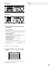
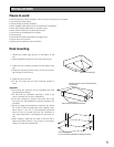
WJ-HD316A/WJ-
HD309A
Unit Address
(System)
Unit Address
(Controller)
First unit
Second unit
Fourth unit
Third unit
001
002
003
004
Number except
001 - 004
(Do not allocate a
number already in
use.)
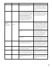
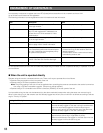
For the system controller
• Set the unit address as follows.
Unit Address Note
Controller used to oper-
ate the first unit
001
It is possible to
operate all of four
units.
Controller used to oper-
ate the second unit
002
It is possible to
operate only moni-
tor 1 connected to
the second unit.
Controller used to oper-
ate the third unit
003
It is possible to
operate only moni-
tor 1 connected to
the third unit.
Controller used to oper-
ate the fourth unit
004
It is possible to
operate only moni-
tor 1 connected to
the fourth unit.
■ Operation using the buttons on
the front panel
It is possible to operate the unit using the buttons on the
front panel as described on pages 18 - 53. When monitor 2
is selected, images will be displayed on monitor 2 connect-
ed to the first unit. When monitor 1 is selected, images will
be displayed on monitor 1 connected to the unit currently in
use.
When operating the buttons on the front panel, only
live/recorded images from the cameras connected to the
unit currently in use are available. It is impossible to oper-
ate live/recorded images from the cameras connected to
the other units.
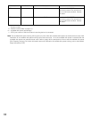
Important:
This example works only when all the system controllers
of the unit address 002 - 004 are the WV-CU650.
If any of the system controller of the unit address 002 -
004 is the WV-CU360C, the camera channel playing on
monitor 2 using the system controller of the unit
address 001 will be changed when playback operation
is performed by the WV-CU360C.
To allow the system controllers of the unit address 002 -
004 to operate only monitor 1 connected to each of the
unit, use the WV-CU650 for the unit address 002 - 004.