13258 11/01
19
ANTENNA CONNECTIONS
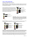
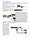
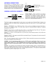
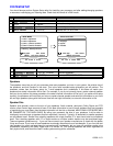
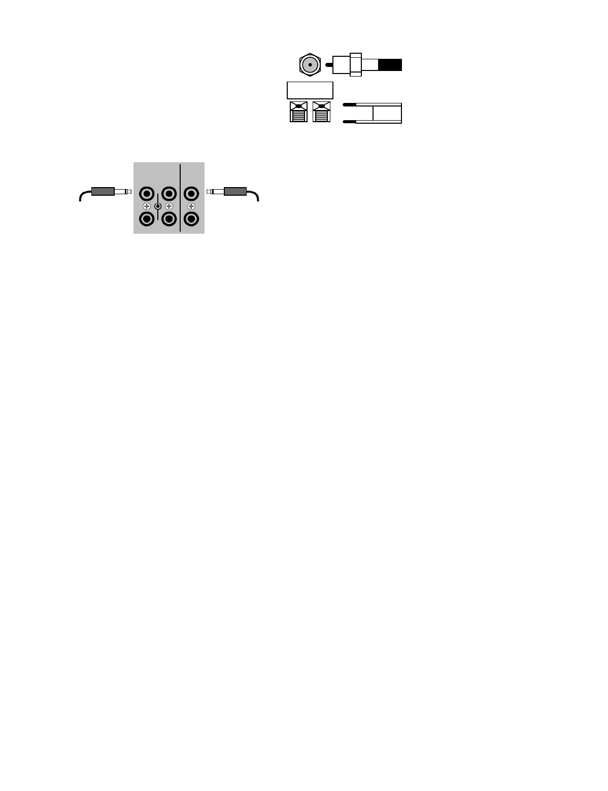
The FM jack is a standard screw on F-type
connector. The AM is a push type. Strip ¼ inch of
insulation off your AM antenna wires and insert one
wire end into each hole while holding the tabs down.
Release the tabs to lock in the AM antenna wires.
CONTROL OUTPUTS / IR INPUTS
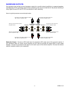
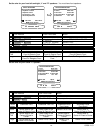
Control Outputs -
These connections are used for
controlling other equipment such as an external B&K
Components, Ltd. amplifier, projection screen, etc.
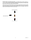
Connect your control cable to the processor using a
mono 3.5 mm jack shown at left. The plug must be
wired as tip (+) and the long barrel section (-).
The Control outputs are programmable for each source in your system (see “Advanced Setup”). However, the
processor provides the following factory preprogrammed setup that should serve for most standard system
applications.
Control 1
- HEADPHONE - On (+12 VDC) when Zone 1 (A) is on and not in Headphone mode, off when Zone 1
(A) is off or in Headphone Mode. This mode may be used for controlling external amplifiers or powered
subwoofers in Zone 1 (A).
Control 2
- Zone 2 (B). On (+12 VDC) when Zone 2 (B) is on, off (0 VDC) when Zone 2 (B) is off. This mode is
used for controlling external amplifiers, projection screens, etc. in Zone 2 (B).
Control 3
- Z1 + Z2. On (+12 VDC) when Zone 1 (A), Zone 2 (B), or both zones are turned on. Off (0 VDC) when
both zones are off.
Control 4
-REMOTE. It will repeat a received 38 kHz modulated IR signal. The processor will transmit received IR
signals even in sleep mode.
Note - The control outputs can output a maximum of 50 mA. Check to see that the source you are connecting to
the control out requires 50 mA or less current.
WARNING - Not all manufacturers adhere to the +12 VDC control specification. Check to see if your
sources control inputs are +12 VDC compatible. Do not connect your processor’s control outputs to a
source with control or remote inputs rated at +5 VDC or other voltage rating. Damage to your source may
result.
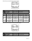
IR Inputs -
Your processor can be controlled by a directly connected IR repeater system in combination with or in
place of the supplied remote control. Connect your IR input cable to the processor using a mono 3.5 mm jack
shown above. The plug must be wired as tip (+) and the long barrel section (-). The inputs are standard 38kHz
modulated IR type with a voltage range of +5 to +12 VDC.
FM antenna
TUNER
AM antenna
FM Antenna Input
from Indoor/Outdoor Antenna,
Cable Box, etc.
AM Antenna Input
from Loop Antenna
CAUTION!
3.5 mm IR in
from remote repeater
CONTROL OUT
1
2
3
4
+12VDC
50mA
IR IN
ZA
ZB
3.5 mm control output
to amplifier, etc.


