


44
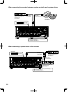
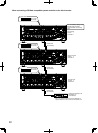
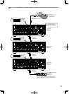
HowtousetheterminalsoftheALARM/CONTROLconnector
These terminals are used for emergency recording, auto time adjustment and when installing a buzzer, a lamp or a similar alarm
device.
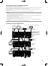
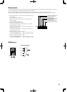
The connector to be used should be compatible with the pin array.
Pin array
The pin array is different from other digital disk recorders. Make sure
that the connection is correct referring to the following.
Pin No. Signal Operation Remarks
1 Alarm output 8 Alarm signal will be supplied at an event occur-
rence
Open collector output
24 V DC max., –100 mA
2 Alarm output 9
3 Alarm output 10
4 Alarm output 11
5 Alarm output 12
6 Alarm output 13
7 Alarm output 14
8 Alarm output 15
9 Alarm output 16
10 N/A
11 Alarm reset input Canceling the alarm display Non-voltage make contact
input/5 V pull-up
12 Emergency recording input Starting emergency recording signal input
13 Signal ground
14 Signal ground
15 Available disk space warning
output
Signal output for available (remaining) disk space
warning of the normal recording area/event
recording area/copy area
Open collector output/
24 V DC max., –100 mA
16 HDD error output Signal output upon detection of an HDD error
17 Camera error output Signal output upon detection of a camera error
18 Error output Signal output upon detection of a recorder error
19 Outage processing end
output
Signal output upon completion of outage pro-
cessing
High (+12 V) 12 mA
20 Time adjustment I/O According to the signal input, the time of this
recorder will be generated as the signal output,
and then the time of all other recorders is adjust-
ed to the time of this recorder.
30 kΩ, 5 V pull-up, Output cur-
rent –100 mA/Non-voltage make
contact input
21 Sequence switchover I/O According to the signal input, the sequence
operation will be switched and the signal output
will be generated upon the sequence switchover.
22 Alarm suspension input The state of the alarm suspension is assigned
according to the signal input.
Non-voltage make contact
input/5 V pull-up, –100 mA
23 Outage detection input Start the outage processing according to the sig-
nal input.
24 External recording mode
switching input
Changeover to the external recording mode
25 +5 V output +5 V output 200 mA max.
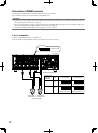
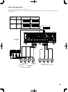
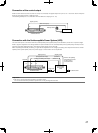
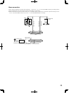
About the connectors
113
25
14
ALARM/CONTROL