


37
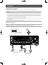
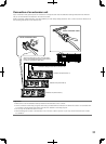
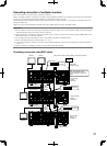
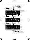
Cascading connection of multiple recorders
Up to 5 recorders can be connected in cascading connection.
When connecting recorders in cascading connection, images displayed on Monitor 2 connected to the second and subsequent
recorders can be switched and displayed on Monitor 2 connected to the first recorder.
Use the cascade input connector, cascade output connector (monitor output connector 2 is provided as the dual purpose con-
nector) and DATA port.
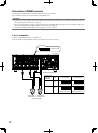
Cables are to be connected differently between when using HDMI cables and when using BNC cables.
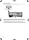
Important:
• Whenmultiplerecordersareconnectingincascadingconnection,select"On"forthe"Cascade"settingonthe[Cascade]tab
under the "Display" page of the setup menu. (+ Page 91)
• Whenconnectingincascadingconnection,allcablesusedtoconnecttothemonitorconnectorshallbeHDMIcablesonlyor
BNC cables only. Do not use them together.
• DonotassignthesameunitaddresstotwoormoredifferentPS·Datacompatibledevices.
• Settheunitaddress(system)oftherecordersto"1"to"5".
• Incascadingconnection,thetimeofrecordersisautomaticallyadjustedtothatoftherecorderwhoseunitaddress(system)
is set to "1".
• Whenconnectingincascadingconnection,allrecordersshallbeWJ-HD616K.
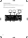
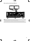
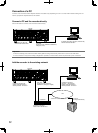
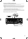
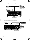
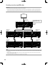
Cascading connection using BNC cables
EXT STORAGE
MODE DATA
RS485(CAMERA)
10/100BASE-T
ALARM
VIDEO
OUT
-
CASCADE
-
INALARM/CONTROL CASCADE IN
MONITOR
OUT
OUT MONITOR OUT(HD) AUDIO IN
AUDIO
OUT
3 2 1
123 45 67 8
1234
4 2
3 1
12
5678910111213141516
IN
OUT
2
1
34567
7
1212
8910111213141516
POWER
AC IN
SIGNAL
GND
ON
OFF
OUT
IN
OUT
CASCADE
1
2
7 8
ON
61 2 3 4 5
7 8
ON
61 2 3 4 5
7 8
ON
61 2 3 4 5
Monitor 2 Monitor 1
Monitor 1
Monitor 1
Mode switch
Mode switch
Mode switch
(No.7: OFF)
(No.8: ON)
(No.7: OFF)
(No.8: OFF)
(No.7: OFF)
(No.8: ON)
* When also connecting audio cables in cascading connection
Powered
speaker
BNC cable
(locally procured)
BNC cable
(locally procured)
BNC cable
(locally procured)
Audio cable
(locally procured)
RS485
cable
(WV-CA
48/50)
RS485
cable
(WV-CA
48/50)
First recorder
System: 1
Controller: 1
Second recorder
System: 2
Controller: 2
Audio cable
(locally procured)
Third recorder
System: 3
Controller: 3
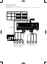
The "Unit address" setting on the
[PS·Data setup] tab under
"Communication" of the setup
menu