


22
Note:
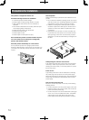
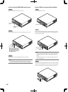
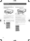
• Afterattachingthefrontcovertotherecorder,besureto
turn on the power of front cover.
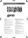
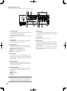
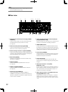
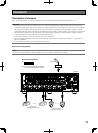
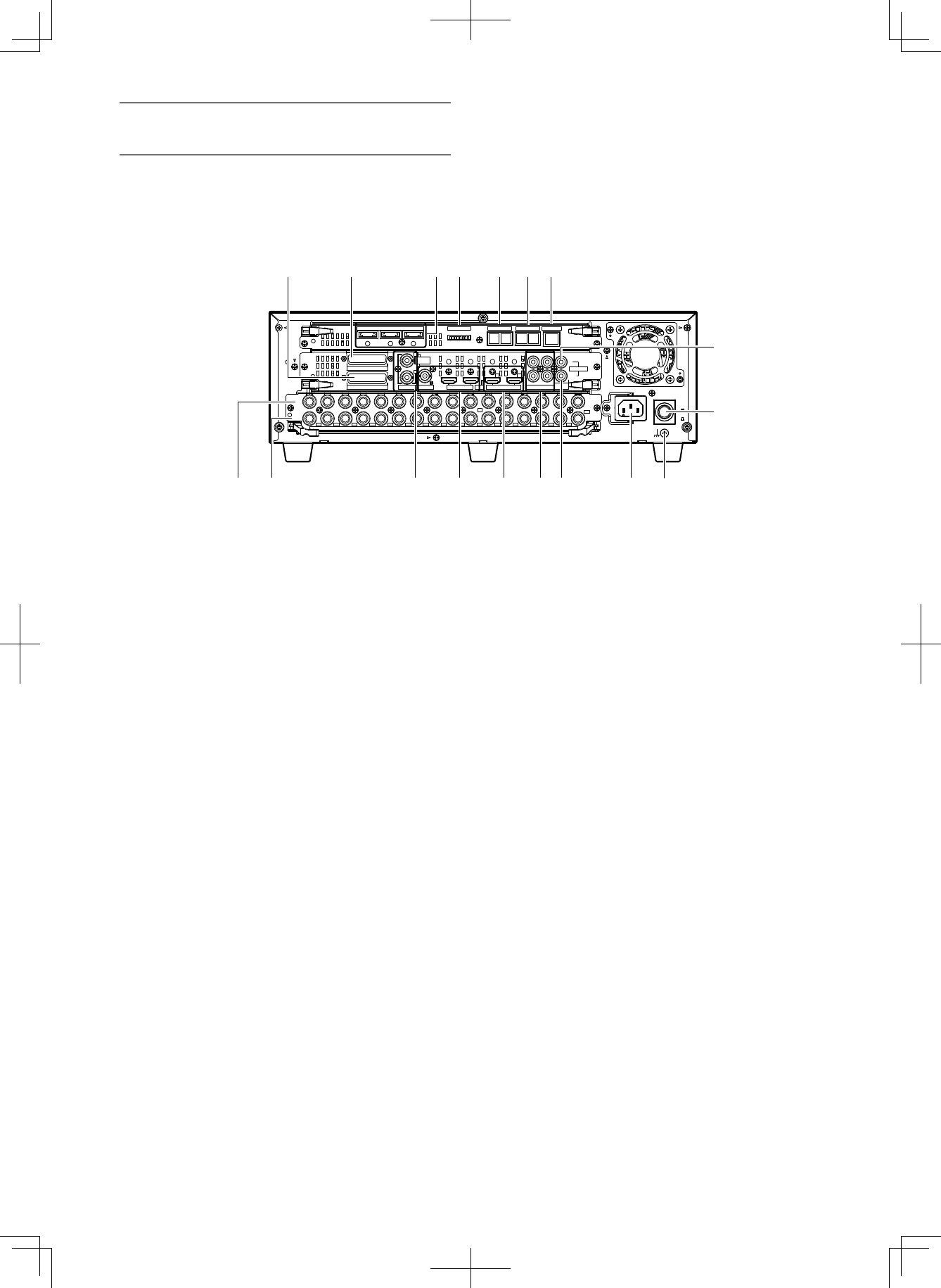
■ Rear view
EXT STORAGE
MODE DATA
RS485(CAMERA)
10/100BASE-T
ALARM
ALARM/CONTROL
VIDEO
OUT
-
CASCADE
-
IN CASCADE IN
MONITOR
OUT
OUT MONITOR OUT(HD) AUDIO IN
AUDIO
OUT
3 2 1
123 45 67 8
1234
4 2
3 1
12
5678910111213141516
IN
OUT
2
1
34567
7
1212
8910111213141516
POWER
AC IN
SIGNAL
GND
ON
OFF
OUT
IN
OUT
CASCADE
1
2
q w e r t y u
!2 !3 !4 !5 !6 !7 !8 !1
i
!0
o
qAlarm/Controlconnector(D-sub25-pin)[ALARM/
CONTROL]
Connect a control switch to control the recorder using
an external device such as a buzzer or a lamp.
(+ Page 44)
wAlarmconnector(D-sub25-pin)[ALARM]
Connect an external device such as a sensor, door
switch, etc. to this connector. (+ Page 48)
eExternalstorageconnector1-3[EXTSTORAGE]
Connect the optional extension unit (WJ-HDE400) to this
connector using the dedicated connection cable provid-
ed with the extension unit. (+ Page 33)
rModeswitch[MODE]
Determine the operational mode of the recorder using
this switch. (+ Page 51)
tDATAport[DATA]
Connect a PS·Data compatible device to this port.
(+ Page 35)
yRS485port[RS485/CAMERA]
Connect an RS485 combination camera to this port.
(+ Page 42)
uNetworkport[10/100BASE-T]
Connect this recorder to a network (10BASE-T/
100BASE-TX) using this port. When the recorder is con-
nected to a network, it is possible to operate the record-
er from a PC via a network.
iAudiocascadeinput/outputconnector(RCApin
jack)[CASCADEIN,OUT])
Use this connector for audio output from another record-
er when it is connected in cascading connection.
o SIGNAL GND terminal
Connect this terminal to the SIGNAL GND terminals of
the devices in the system for signal ground. When oper-
ating the recorder and the devices in the system without
signal ground, oscillation or noise may be produced.
!0Powerbutton[POWER]
Press this button to turn on/off the power of the record-
er. When this button is pressed again, the operation is
finished and the power is turned off.
!1Powerinlet[ACIN]
Connect the provided power cord to this inlet. The
power plug is a 2-conductor plug with grounding termi-
nal type.
!2Videoinputconnector1to16(BNC)
[VIDEOIN1to16]
Connect system cameras and combination cameras to
these connectors. When connecting combination cam-
eras, connect them to the video input connector 1-8
(coaxial communication compatible).
!3Videooutputconnector1to16(BNC,activeloop
through)[VIDEOOUT1to16]
Images input to the video out connectors 1-16 will be
output from these connectors. When the power is off,
images will not be output to the video output connector
1-16.