


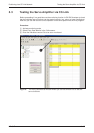

A Appendix
A.1
Digital Signals
Quick Reference
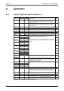
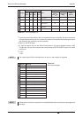
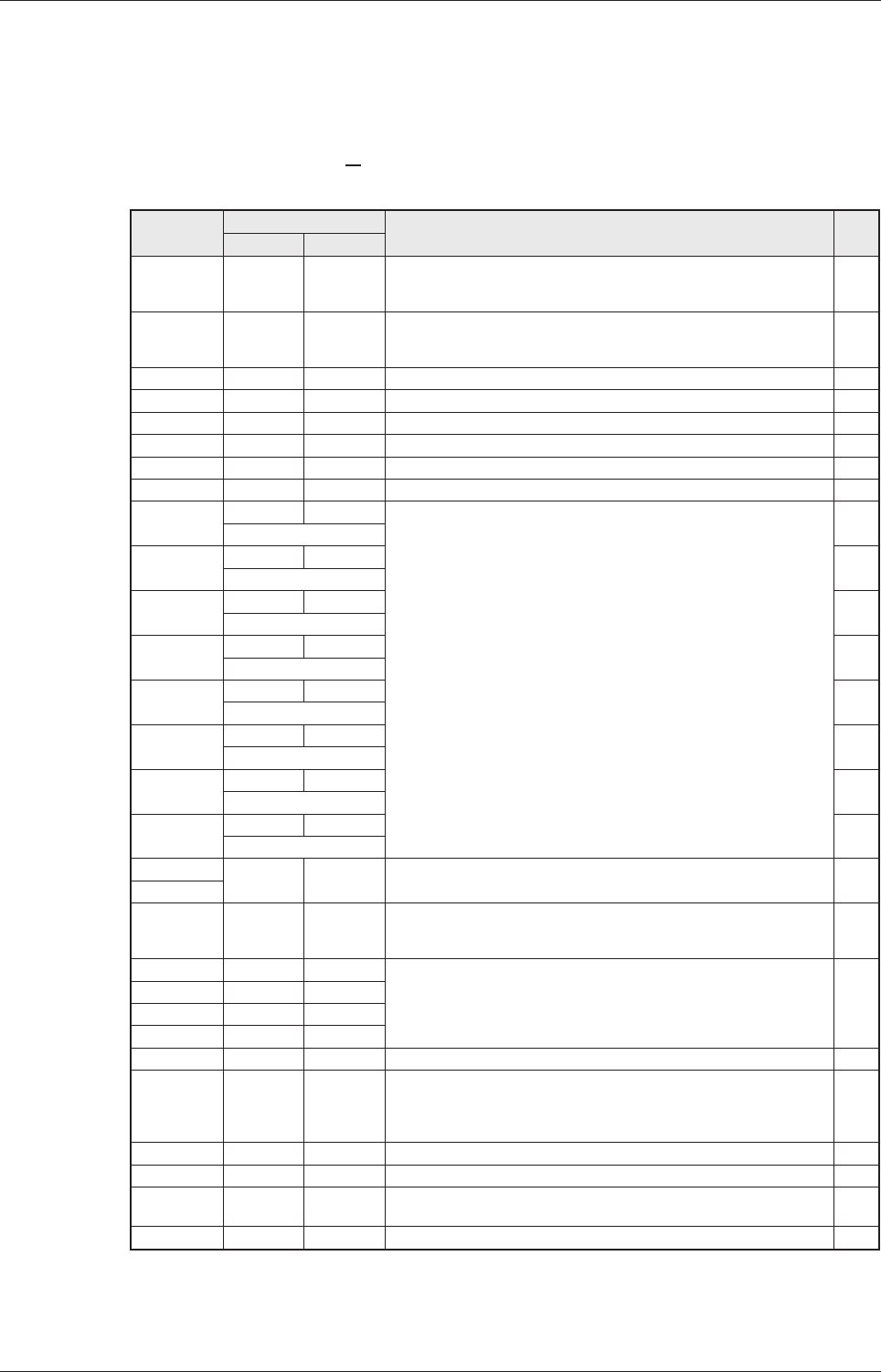
Appendix Digital Signals − Quick Reference
MR-J3-T A-39
Connector
Pins
Signal Codes
Description
DI /
DO
DI/DO CC-Link
CN6-1 EMG – Forced stop - emergency safety signal:
The signal is permanently assigned to this pin and must be acti-
vated for motor control.
DI
CN6-2 DOG RYn3 Proximity dog switch:
This signal is used for some of the home position return modes.
(See chapter 4.3)
DI
CN6-3 LSP RYn4 Forward rotation stroke end switch DI
CN6-4 LSN RYn5 Reverse rotation stroke end switch DI
CN6-14 RD RXn0 Servo amplifier ready DO
CN6-15 ALM RX(n+1)A Alarm, signals a servo error DO
CN6-16 ZP RXn3 Home position return completed successfully DO
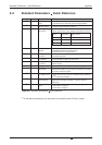
CN10-1 DI0 RYnA Select point table entry, i.e. activate a line in the table for position-
ing. Combinations of signals DI0 through DI7 (see Table 4-3) can
be used to selec up tot 256 positioning steps.
NOTE:
Signals DI5, DI6 and DI7 are only available when the amplifier oc-
cupies 2 stations in the network, thus making 64 bits available via
CC-Link.
DI
Point table entry no.1
CN10-2 DI1 RYnB DI
Point table entry no. 2
CN10-3 DI2 RYnC DI
Point table entry no. 3
CN10-4 DI3 RYnD DI
Point table entry no. 4
CN10-5 DI4 RYnE DI
Point table entry no. 5
CN10-6 DI5 RY(n+2)3 DI
Point table entry no. 6
CN10-7 DI6 RY(n+2)4 DI
Point table entry no. 7
CN10-8 DI7 RY(n+2)5 DI
Point table entry no. 8
CN10-13 DICOM – Connection for an external power supply for the digital control termi-
nals. Negative connection for source interface logic (PNP).
DI
CN10-14
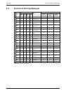
CN10-21 SON RYn0 SERVO ON:
Activating the SON signal powers on the base circuit and makes
the amplifier ready for operation.
DI
CN10-22 ACD0 – Digital output signals for encoded error messages (see Appendix
A.3)
DO
CN10-23 ACD1 –
CN10-24 ACD2 –
CN10-25 ACD3 –
CN10-26 RES RY1A Reset for error messages DI
CN10-32 MD0 RYn6 Switch between automatic/manual mode:
The MD0 signal must be off for opertion in jog mode. The signal
must be activated before starting a home position return or position
-
ing.
DI
CN10-35 ST1 RYn1 Start signal for forward rotation DI
CN10-36 ST2 RYn2 Start signal for reverse rotation DI
CN10-37 DOCO – Connection for an external power supply for the digital control termi
-
nals. Positive connection for source interface logic (PNP).
DI
CN10-49 INP RXn1 IN Position: Target position reached signal. DO
Table A-1: Digital signals - quick reference