ብ
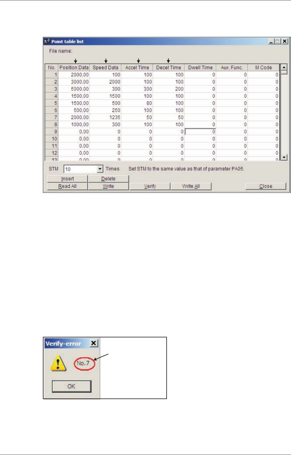
The point table entries for the individual positioning steps are configured in the columns
numbered ᕡ to ᕤ in the point table list shown below.
Tips for editing point table entries:
b The value in the
Aux.Func.
column should normally always be zero.Otherwise the system
will automatically jump to the next entry in the table and execute the next positioning com-
mand after completing a positioningstep, even if there is no change inthe input signals.
b The
Dwell Time
column can be used to insert a delay between reaching the target position
of the positioning step for the current table line and continuing to the next table line. This
option should only be used when multiple positioning steps are performed automatically,
without changes in the input signals.
b The button
Insert
inserts a new line above the selected table line.
Delete
deletes the se-
lected line.
b The Verify function checks whether the positioning table in MR Configurator matches the
table stored in the connected servo amplifier. If the tables don't match a message is dis-
played showing the line number where the difference was found:
Positioning with Digital Inputs Configuration for Positioning
MR-J3-T 4-25
Fig. 4-15: Example of a positioning application with 8 positioning steps
ᕡ
ᕢ
ᕣ
ᕤ
Number of table line
where tables in amplifier
and MR-Configurator do
not match


