


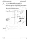

4.4 Configuration for Positioning
If you install the MR-J3-D01 I/O expansion you can use point table positioning, which allows you
to select positions from a list of up to 256 table entries with a combination of eight digital inputs.
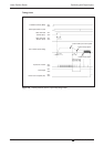
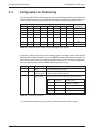
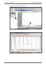
Table 4-3 shows how binary input signals are encoded to address the point table entries.
In the factory default configuration the incremental system is activated, which means that the
absolute position detection system is turned off (PA03 “absolute position detection system”).In
this mode the current position is not stored when the power is turned off and you must thus per-
form a home position return every time the amplifier is powered on. The default configuration
also uses absolute target positions (PA01 “positioning control mode”).
ቢ
To activate this parameter you must switch the amplifier power off and on again.
Positioning with Digital Inputs Configuration for Positioning
MR-J3-T 4-23
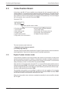
Digital Input Signals
Selected Point
Table Entry
DI7 DI6 DI5 DI4 DI3 DI2 DI1 DI0
00000001 1
00000010 2
00000011 3
00000100 4
·
·
·
·
·
·
·
·
·
·
·
·
·
·
·
·
·
·
·
·
·
·
·
·
·
·
·
11111110 254
11111111 255
Table 4-3: Selection of point table entries with digital input signals
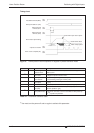
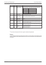
No. Code Function Description
PA01
ቢ
*STY Positioning control
mode
0: Absolute target position values
1: Incremental target position values
PA03
ቢ
*ABS Absolute position
detection system
0: Incremental system (absolute detection off)
1: Absolute position detection system on
PA05
ቢ
*FTY Feed length multi-
plication factor
Needed here to scale the home position value to the physical coor-
dinate system when a home position offset (shift) has been set.
Table 4-4: Parameter reference
Parameter
value
Multiplication
factor STM
Range of the target
position values
01
−999.999 .. +999.999
110
−9999.99 .. +9999.99
2 100
−99999.9 .. +99999.9
3 1000
−999999 .. +999999