


Contents
ii MITSUBISHI ELECTRIC
1 Introduction
1.1 Preparations . . . . . . . . . . . . . . . . . . . . . . . . . . . . . . . . . . . . . . . . . . . . . . . . . . . . .1-1
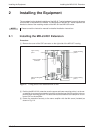
2 Installing the Equipment
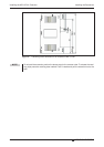
2.1 Installing the MR-J3-D01 Extension . . . . . . . . . . . . . . . . . . . . . . . . . . . . . . . . . . .2-3
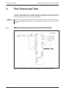
3 First Functional Test
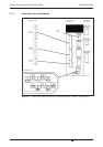
3.1 Minimum Connections for the Functional Check . . . . . . . . . . . . . . . . . . . . . . . . . . . . . 3-5
3.1.1 Connector pin assignments. . . . . . . . . . . . . . . . . . . . . . . . . . . . . . . . . . .3-6
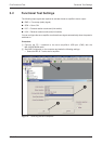
3.2 Functional Test Settings. . . . . . . . . . . . . . . . . . . . . . . . . . . . . . . . . . . . . . . . . . . . .3-7
3.3 Configuring Positioning Point Tables . . . . . . . . . . . . . . . . . . . . . . . . . . . . . . . . . . .3-9
3.4 Functional Test with MR Configurator . . . . . . . . . . . . . . . . . . . . . . . . . . . . . . . . .3-10
3.4.1 Selecting point table position entries . . . . . . . . . . . . . . . . . . . . . . . . . .3-10
4 Positioning with Digital Inputs
4.1 Additional Connections . . . . . . . . . . . . . . . . . . . . . . . . . . . . . . . . . . . . . . . . . . . .4-11
4.2 Turning off Automatic Input Signal Activation . . . . . . . . . . . . . . . . . . . . . . . . . . . 4-14
4.3 Home Position Return. . . . . . . . . . . . . . . . . . . . . . . . . . . . . . . . . . . . . . . . . . . . .4-15
4.3.1 Dogless Z-phase reference mode. . . . . . . . . . . . . . . . . . . . . . . . . . . . .4-15
4.3.2 Dog mode home position return . . . . . . . . . . . . . . . . . . . . . . . . . . . . . .4-19
4.4 Configuration for Positioning . . . . . . . . . . . . . . . . . . . . . . . . . . . . . . . . . . . . . . . .4-23
4.4.1 Importing and exporting point tables. . . . . . . . . . . . . . . . . . . . . . . . . . .4-26
4.5 Functional Test of Digital Input Positioning . . . . . . . . . . . . . . . . . . . . . . . . . . . . . .4-28
5 Positioning via a CC-Link Network
5.1 Additional Connections . . . . . . . . . . . . . . . . . . . . . . . . . . . . . . . . . . . . . . . . . . . .5-31
5.2 CC-Link Communication Settings . . . . . . . . . . . . . . . . . . . . . . . . . . . . . . . . . . . .5-33
5.2.1 Settings on the servo amplifier . . . . . . . . . . . . . . . . . . . . . . . . . . . . . . .5-33
5.2.2 Configuration for communication with GX IEC Developer . . . . . . . . . . 5-35
5.3 Testing the Servo Amplifier via CC-Link . . . . . . . . . . . . . . . . . . . . . . . . . . . . . . .5-37
A Appendix
A.1 Digital Signals − Quick Reference. . . . . . . . . . . . . . . . . . . . . . . . . . . . . . . . . . . .A-39
A.2 Standard Parameters − Quick Reference . . . . . . . . . . . . . . . . . . . . . . . . . . . . . .A-40
A.3 Alarms and Warning Messages . . . . . . . . . . . . . . . . . . . . . . . . . . . . . . . . . . . . . . .A-41