


4 Positioning with Digital Inputs
This chapter describes how pointtable positioning is usedin most applications with the MR-J3-T
series amplifiers and the MR-J3-D01 I/O extension.
NOTE Please refer to the instruction manualif you need other functions other than those described
here for your application.
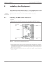
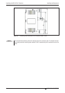
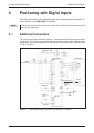
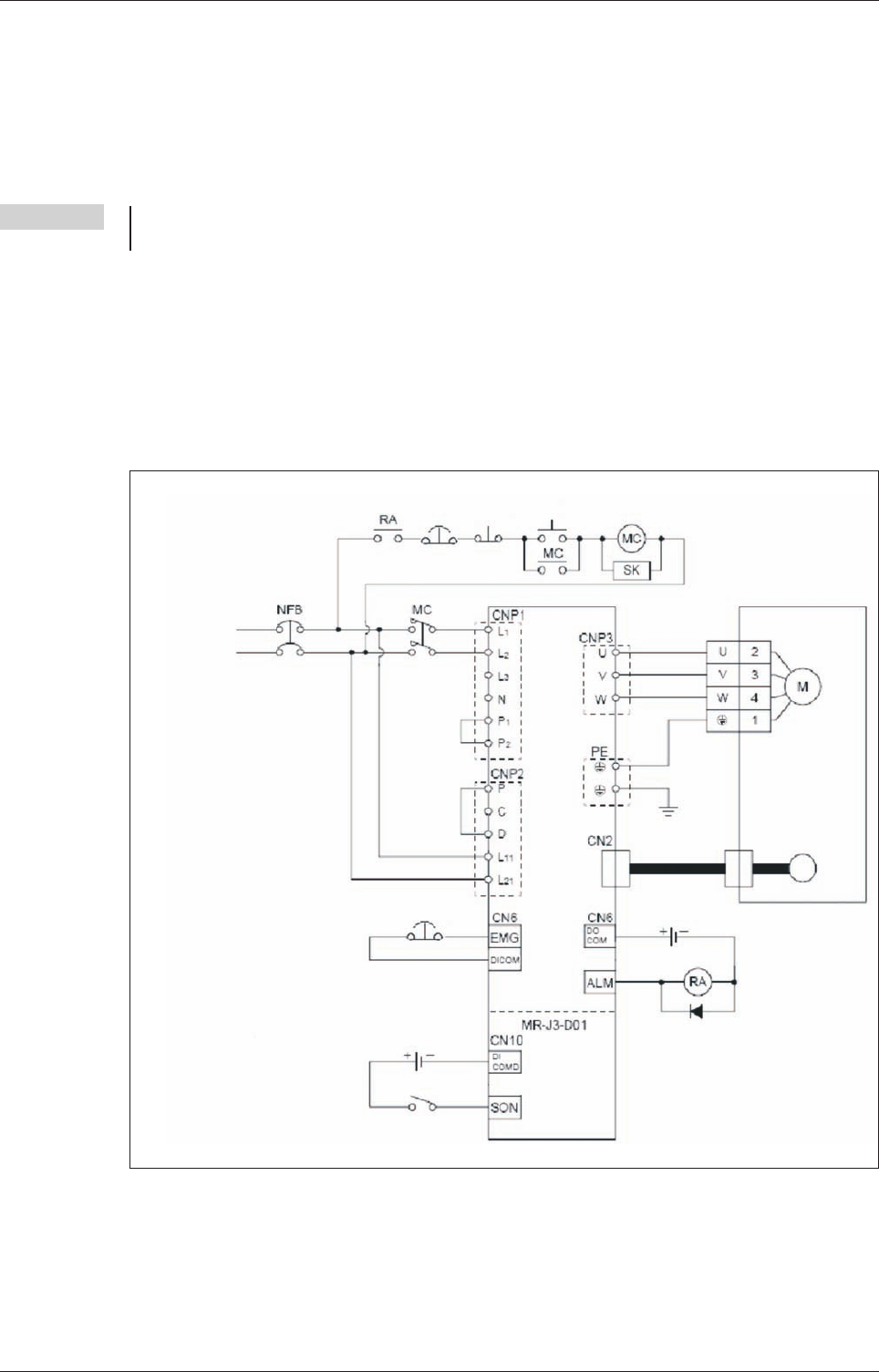
4.1 Additional Connections
The initial functional tests described in chapter 3.1 were performed with a minimum connection
configuration. For the full range of standard functions you now need to make additional power
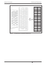
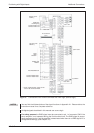
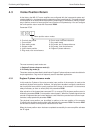
supply and control terminal connections on the CN6 and CN10 terminal blocks, as shown below
in Figs. 4-1 and 4-2.
Positioning with Digital Inputs Additional Connections
MR-J3-T 4-11
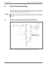
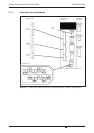
Fig. 4-1: Single-phase power connections for the MR-J3-T amplifier
1-phase
200–230V AC
Servo motor
Motor
Encoder
Encoder cable
Alarm
EMG. OFF
OFF
ON
EMG. OFF
Servo ON
Servo amplifier
24V DC
24V DC ± 10 %
800 mA
24V DC
24V DC ±10%
150mA