


3 First Functional Test
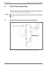
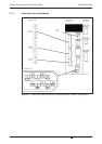
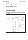
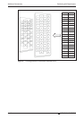
The wiring diagram below (Fig. 3-1) shows the minimum connections that you must make to test
an MR-J3-T series amplifier with the MR Configurator setup software. In test mode you can
check whether all the components are working properly.
NOTE You can also use the optional MR-PRU-03 HMI control terminal for performing initial tests
and setting theamplifier’s parameters.For further details see theMR-J3-T seriesinstruction
manual.
3.1 Minimum Connections for the Functional Check
First Functional Test Minimum Connections for the Functional Check
MR-J3-T 3-5
Fig. 3-1: Wiring diagram for minimum configuration without control terminals
1-phase
200–230V AC
Servo motor
Motor