


NOTES You can find a brief descriptions of the signal functions in Appendix A.1.Please refer to the
instruction manual for a complete reference.
All digital signals described in this manual use source logic.
For safety reasons the EMG signal must be connected to pin 1 of connector CN6 if the
servo amplifier is not operated during the first functional test. The EMG signal is perma
-
nently assigned to pin 1 and the amplifier is deactivated when there is no EMG signal if it is
configured accordingly (see chapter 3.2).
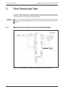
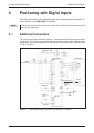
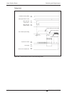
Positioning with Digital Inputs Additional Connections
MR-J3-T 4-13
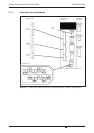
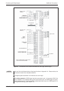
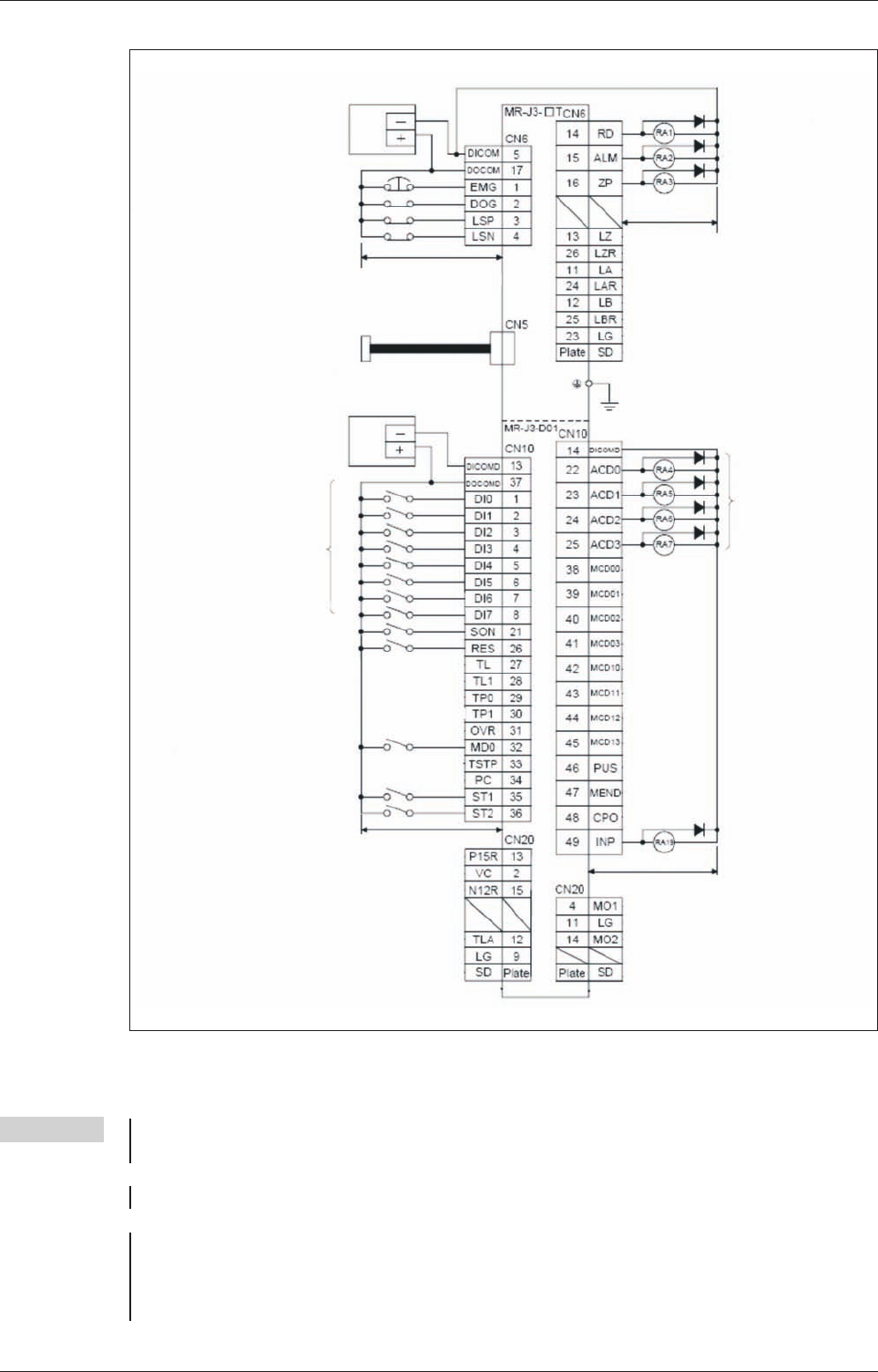
Fig. 4-3: Connection of the control terminals with PNP logic (source logic)
24V DC ±10%
150mA
ቢ
24V DC
EMG. OFF
Proximity dog
Forward stroke end
Reverse stroke end
max. 10m
max. 10m
24V DC ±10%
800mA
ቢ
24V DC
Point
table
selection
SERVO ON
RESET
Automatic/Manuall
Forward rotation start
Reverse rotation start
ቢ
A 24V 1000mA power supply can be
used for all control terminals.
max. 10m
In position
Alarm code
MR-J3USBCBL3M
(Option)
max.10 m