


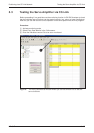

A.2
Standard Parameters
Quick Reference
ቢ
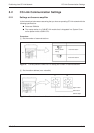
To activate this parameter you must switch the amplifier power off and on again.
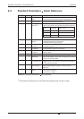
Standard Parameters − Quick Reference Appendix
A-40 MITSUBISHI ELECTRIC
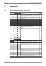
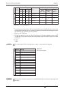
No. Code Function Description
PA01
ቢ
*STY Positioning control
mode
0: Absolute value command system for target positions
1: Incremental value command system for target positions
PA03
ቢ
*ABS Absolute position
detection system
0: Incremental system (absolute position detection off)
1: Absolute position detection system on
PA05
ቢ
*FTY Feed length multipli
-
cation factor
Needed here to scale the home position value to the physical co
-
ordinate system when a home position offset (shift) has been set.
PA14
ቢ
*POL Servo motor rotation
direction
Motor rotation direction (looking at shaft end facing motor):
0: Anticlockwise when ST1 signal is active
1: Clockwise when ST1 signal is active
PC02
ቢ
*ZTY Home position re-
turn mode
Selects mode to be used for home position return:
0: Proximity dog mode
PC03
ቢ
*ZDIR Home position re-
turn direction
0: Incrementing counting of encoder pulses
1: Decrementing counting of encoder pulses
PC04 ZRF Home position re-
turn speed
Sets home position return speed until first detection of the
Z-phase in [rpm].
PC05 CRF Creep speed Speed for precise movement to home position in [rpm]
PC06 ZST Home position
offset (shift)
Distance between the encoder home position (Z-phase) and the
physical home position in [µm]. Does not change the zero point of
the physical coordinate system.
PC07
ቢ
*ZPS Home position re-
turn position value
The home position return stops when the Z-phase position is
reached.You can enter a non-zero coordinate for this position [in
10
STM
µm] with this parameter.
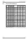
PD01
ቢ
*DIA1 Automatic activation
of input signals
This parameter configures the amplifier to automatically set the
digital signals internally to a logical "1" when the power is
switched on.
PD01
ቢ
*DIAB Polarity of the input
signal
Logical value for detection of the proximity dog signal (DOG):
0: Active DOG on logical "0"
1: Active DOG on logical "1"
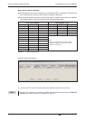
Table A-2:
Standard parameters
quick reference
Parameter
value
Multiplication
factor STM
Range of the target
position values
01
−999.999 ... +999.999
110
−9999.99 ... +9999.99
2 100
−99999.9 ... +99999.9