


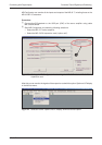
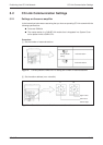
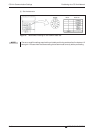
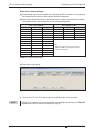

Notes on the network settings:
(a) Intheexample only one servoamplifier is connected to theCC-Link network. This value must
be increased by the number of slave stations installed if applicable.
(b)These values specify which bits or data words are to be used to control the servo amplifier.
The settings shown in the example are for the following assignments:
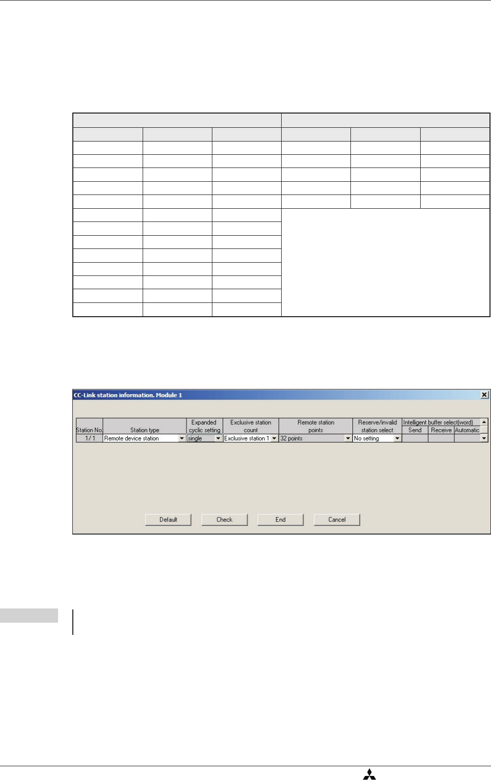
(c) Slave station type setting:
ብ
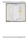
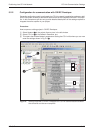
Connect the PC to the PLC and transfer the modified project to the controller.
NOTE If the CC-Link connection to the servo amplifier is established successfully the L.RUN, SD
und RD status LEDs on the servo amplifier will light up.
CC-Link Communication Settings Positioning via a CC-Link Network
5-36 MITSUBISHI ELECTRIC
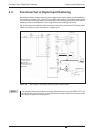
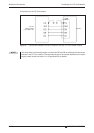
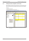
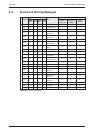
Fig. 5-7: This configuration also enables exchange of data words
PLC -> Servo Amplifier Servo Amplifier -> PLC
PLC I/Os Registers Signals PLC I/Os Registers Signals
Y100 RYn0 SON X100 RXn0 RD
Y101 RYn1 ST1 X101 RXn1 INP
Y102 RYn2 ST2 X103 RXn3 ZP
Y103 RYn3 DOG X11A RX(n+1)A ALM
Y104 RYn4 LSP
Y105 RYn5 LSN
NOTE:
Signals DI5, DI6 and DI7 are only available
when the amplifier is configured to occupy 2
stations in the network.
Y106 RYn6 MD0
Y10A RYnA DI0
Y10B RYnB DI1
Y10C RYnC DI2
Y10D RYnD DI3
Y10E RYnE DI4
Y10F RYnF RES
Table 5-1: Signal assignments