


30
16 IR INPUT
A
1
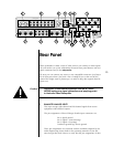
⁄8" “mini” jack labeled ir input near the lower right corner of the rear
panel provides direct access to the infrared control circuitry of the AVP2. It
may be configured during setup (in an on screen menu) to interpret in-
coming signals in either of two ways:
• Remote: when in Remote mode, the AVP2 will interpret any com-
mand entering through the remote IR jack as being intended to
affect the
record/remote path only. This feature allows easy ac-
cess to all sources connected to the AVP2 from elsewhere in the
house with the addition of any commercially-available IR repeater.
• Local: when in the Local mode the remote IR jack responds to
all commands, as the infrared receiver in the main display of the
front panel would. This mode is most often used with an IR re-
peater when the AVP2 and other components are placed inside
of cabinets (preventing the normal IR receiver from receiving re-
mote commands). (See The Setup Menu.)
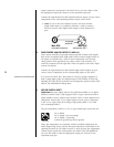
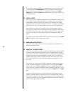
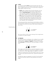
The incoming signal for the remote IR input should conform to widely-ac-
cepted IR repeater standards: that is, the signal present should be between
3-15 volts DC at less than 100 mA current, with a positive tip polarity, as
shown below:
IR input tip polarity
+–
5-12 volts @ less
than 100 mA
Your Proceed dealer can help you take advantage of these design features
to maximize your system’s versatility.
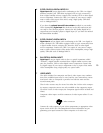
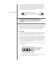
17 DC TRIGGERS
Each of the two remote on/off triggers can be configured by your installer
to provide either 5V or 12V DC trigger signals, either in response to the
AVP2 coming out of standby into operate, or in response to an indepen-
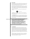
dent IR command. The tip polarity for each of these triggers is as shown
below:
+–
5-12 volts @ less
than 100 mA
These triggers provide some degree of control and automation over prod-
ucts that lack more sophisticated communications capabilities. For example,
you could have one of these triggers toggle your amplifier(s) on and off ac-
cording to the operational status of the AVP2, while the other served to lower
the screen for your projection television when a particular IR command was
received.
By default, these triggers are programmed to provide 12V “level” signals that
are tied to the state of the AVP2: 12V when operational, and 0V when in
standby.