


26
Installation Note: S-video (Y/C) signals are more susceptible to degradation
over long wire runs. The quality of wire used makes a
significant difference, but regardless, it is generally
inadvisable to run S-video cables more than twenty feet (6
meters). Composite video signals tend to hold up better over
longer runs, especially when high quality 75
Ω
cable such as
Madrigal MDC-2 is used.
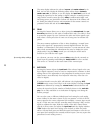
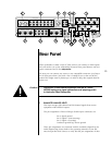
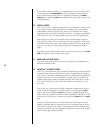
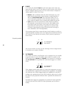
8 BALANCED MAIN OUTPUTS (L, C, R)
The pin assignments of these XLR-type male outputs conform to the inter-
national AES standard, and are as follows:
12
3
Pin 1: Signal ground
Pin 2: Signal + (non-inverting)
Pin 3: Signal – (inverting)
Connector ground lug: chassis ground
Refer to your power amplifier’s operating manual to verify that the pin as-
signments of its input connectors correspond to the Audio Video Preampli-
fier. If not, wire the cable so that the appropriate output pin connects to the
equivalent input pin, or reverse the leads of both your speaker cables to “re-
verse the reversal” and restore correct polarity.
High quality single-ended outputs are also provided for compatibility with
power amplifiers lacking balanced inputs.
Connect the left-front, center and right-front outputs of the Audio Video
Preamplifier to the corresponding inputs on your power amplifier(s).
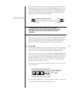
9 SINGLE-ENDED MAIN OUTPUTS (ALL CHANNELS)
The first six of these eight RCA connectors provide the main 5.1 channels
normally associated with a high quality multichannel system: the left-front,
center and right-front outputs of the AVP2 are duplicated here in single-
ended form (for compatibility with power amplifiers lacking any balanced
input capabilities), along with the left-surround, right-surround and
subwoofer channels. Connect these outputs to the corresponding power
amplifier channels.
In addition, two “auxiliary” output channels are provided, labelled aux 1
and aux 2. These channels are used for any of several applications such as
support for 7.1 channel systems (using either separate side and rear chan-
nels Dual Drive™ surrounds), or as additional subwoofer channels. Select
the best use for your particular system in the Setup Menu, according to
your speaker configuration.
10 REMOTE ZONE OUTPUTS
The AVP2 includes a second signal path (beyond the primary one used in
the main listening room) that can feed a remote zone, or a record path for
making recordings, or both. There is one limitation: the remote and record
outputs always contain the same signal.