


20
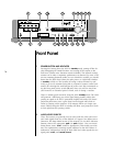
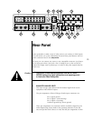
The main display indicates the selected source and master volume by de-
fault, and can also display the following offsets when chosen: balance,
center, rear, sub. In addition, it can also display the input level (used in cali-
brating the input level to the analog to digital converter on analog sources
only) and the overall system (lip-sync) delay in milliseconds. Right- and
Left-facing arrows are provided to indicate the direction of the balance off-
set. Finally, the infrared receiver and transmitter for the remote control are
positioned on the left side of the
main display.
10 DELAY
Pressing this button allows you to adjust (using the volume knob) the sys-
tem delay
introduced to the audio, in milliseconds (mS). This delay is used
to restore the proper “lip sync” between the audio and video signals, espe-
cially when a video processor of some sort is being used to enhance the
picture.
The most common application of this is when displaying a “normal” inter-
laced video signal on a progressively-scanned digital television. The “line
doublers” or deinterlacers used always introduce a certain amount of video
delay while accumulating the information they need to display the video
progressively. Using the delay control, you can delay the audio until it
sounds in sync with the video again.
tip: saving delay settings
As a shortcut, you may save the current delay setting for the currently-se-
lected input by pressing and holding the delay button for a few seconds.
This serves as a shortcut to the menu item for the current input.
11 INPUT LEVEL
Pressing this button adjusts the input level of the selected signal to the ana-
log to digital converter. It may be used to compensate for variations in level
among sources. This adjustment is only important for analog sources (since
digital sources were effectively “level adjusted” when they were first con-
verted to digital).
If overload should occur, the AVP2 will indicate it by displaying ADC
CLIPPING
on the screen (and “Clip!” in the main display). Pressing the input
level
button followed by turning the volume knob counterclockwise will
reduce the input level by the number of decibels shown in the main dis-
play
. Do so only until there is no indication of clipping, even during the
loudest passages.
You can also create a different, default input level setting for each analog
source defined in the menu system. If you can generate a 1 kHz, 0 dB ref-
erence signal in the source component (for example, a cassette tape record-
ing of a 1 kHz test tone, with the recording meters showing 0 dB), use this
signal to calibrate the input. With the volume of the AVP2 turned down,
play the 0 dB test tone, and adjust the input level until the display indicates
“Clip!” Reduce the input level setting a few decibels to allow for peaks
above 0 dB, and then press and hold the input level button to save the cur-
rent input level setting for the currently-selected input. (You may repeat this
procedure for each analog source.)