


23
L
R
R
A1
A2
LR
RR
C
S
L
R
R
PROC E E D
audio video preamplifier
made in u.s.a. by
b
R L
L
1 2345678 1 23
45
67
C L R L
digital
output
control
control ports
PHASTLink™ compatible
RS-
232
ir
input
1 2
triggers
outputs
12
3
12
3
21
3
21
3
21
3
PUSH
21
3
21
3
12
3
R
L
1
6
2
7
3
5 8
4
L
R
~AC mains
video
inputs
main
video
outputs
remote/record
video outputs
digital inputs
record
remoteanalog outputs
analog inputs
8
21 43 5 6 7
9 10 11 12 14 15
16
17 19
18
13
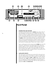
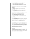
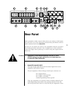
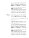
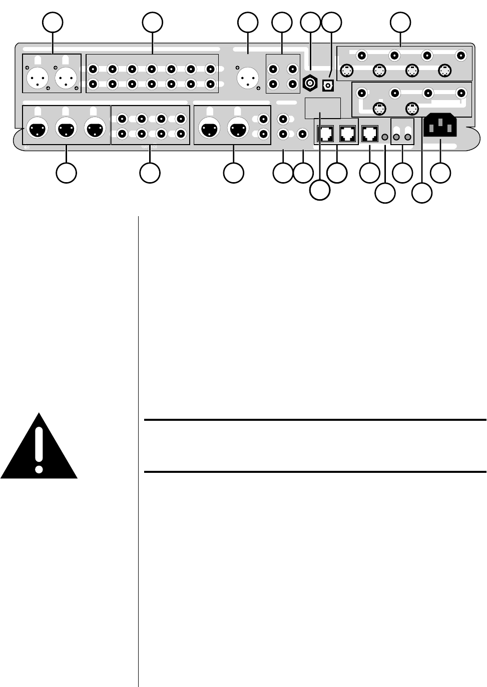
Rear Panel
Please remember to make a note of what sources you connect to which inputs.
You will need to set up the relationships between front panel buttons and rear
panel connectors later, in the setup menu.
For now, you can connect any source to any compatible connector—just keep a
list of what-goes-where. (Just such a list is waiting for you at the end of this
manual. You might want to photocopy it in order to keep the original clean for
future use.)
Caution! Disconnect all associated equipment from the AC mains
BEFORE making any signal connections and applying power
to the Audio Video Preamplifier.
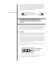
1 BALANCED ANALOG INPUT 1
This input accepts right-channel and left-channel signals from source
equipment with balanced outputs.
The pin assignments of these XLR-type female input connectors are:
Pin 1: Signal ground
Pin 2: Signal + (non-inverting)
Pin 3: Signal – (inverting)
Connector ground lug: chassis ground
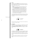
These pin assignments are consistent with the standards adopted by the
Audio Engineering Society. Refer to the operating manuals of your bal-
anced-output line-level sources to verify that the pin assignments of their