


24
output connectors correspond to the AVP2. If not, wire the cables so that
the appropriate output pin connects to the equivalent input pin.
Connect the right-channel and left-channel balanced outputs of your source
components to the corresponding balanced inputs on the AVP2.
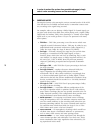
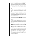
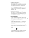
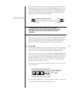
• Note: If you do not have balanced sources and need another
single-ended input, it is possible to fabricate a cable to connect
line-level sources with single-ended output to these balanced in-
puts:
1
2
3
Male RCA
(connect to source)
Male XLR
(connect to AVP)
22-gauge
bus wire
2 SINGLE-ENDED ANALOG INPUTS 2-5 AND 6-8
These inputs normally accept right-channel and left-channel audio signals
from source equipment with single-ended (RCA) outputs. Single-ended au-
dio inputs are provided for a total of seven components. Note that the
video portion of the signal from any video source (VCR, laserdisc, TV)
would be connected on the right side of the rear panel, in the Video Input
section. (See below.)
Connect the right-channel and left-channel single-ended outputs of your
various source components to the corresponding inputs on the AVP2.
optional six channel input
If you have the “AVP2 Plus,” then inputs 6-8 may be “ganged together” to
form a single, high quality, six-channel input for DVD-Audio or SACD. Sig-
nificantly, all of the AVP2’s powerful bass management options remain avail-
able for this multichannel analog input.
3 AES/EBU DIGITAL INPUT 1
Digital Input 1 accepts digital audio in the professional 110Ω AES/EBU digital
interface standard (via a cable equipped with XLR-type connectors) from a
digital satellite receiver, compact disc, laserdisc, DVD or other digital source
component. Connect the AES/EBU digital output of your source component
to the AES/EBU input of the AVP2 using a high quality 110Ω AES/EBU cable
such as Madrigal MDC-1.
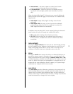
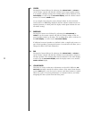
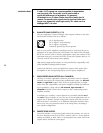
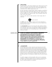
The pin assignments of these AES/EBU XLR-type female input connectors are:
PUSH
21
3
Pin 1: Shield
Pin 2: Digital + (non-inverting)
Pin 3: Digital – (inverting)
Connector ground lug: chassis ground
These pin assignments are consistent with the standards adopted by the
Audio Engineering Society and the European Broadcast Union. Refer to the
operating manuals of your digital sources to verify that the pin assignments
of their output connectors correspond to the Audio Video Preamplifier. If
not, wire the cables so that the appropriate output pin connects to the
equivalent input pin.