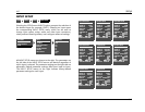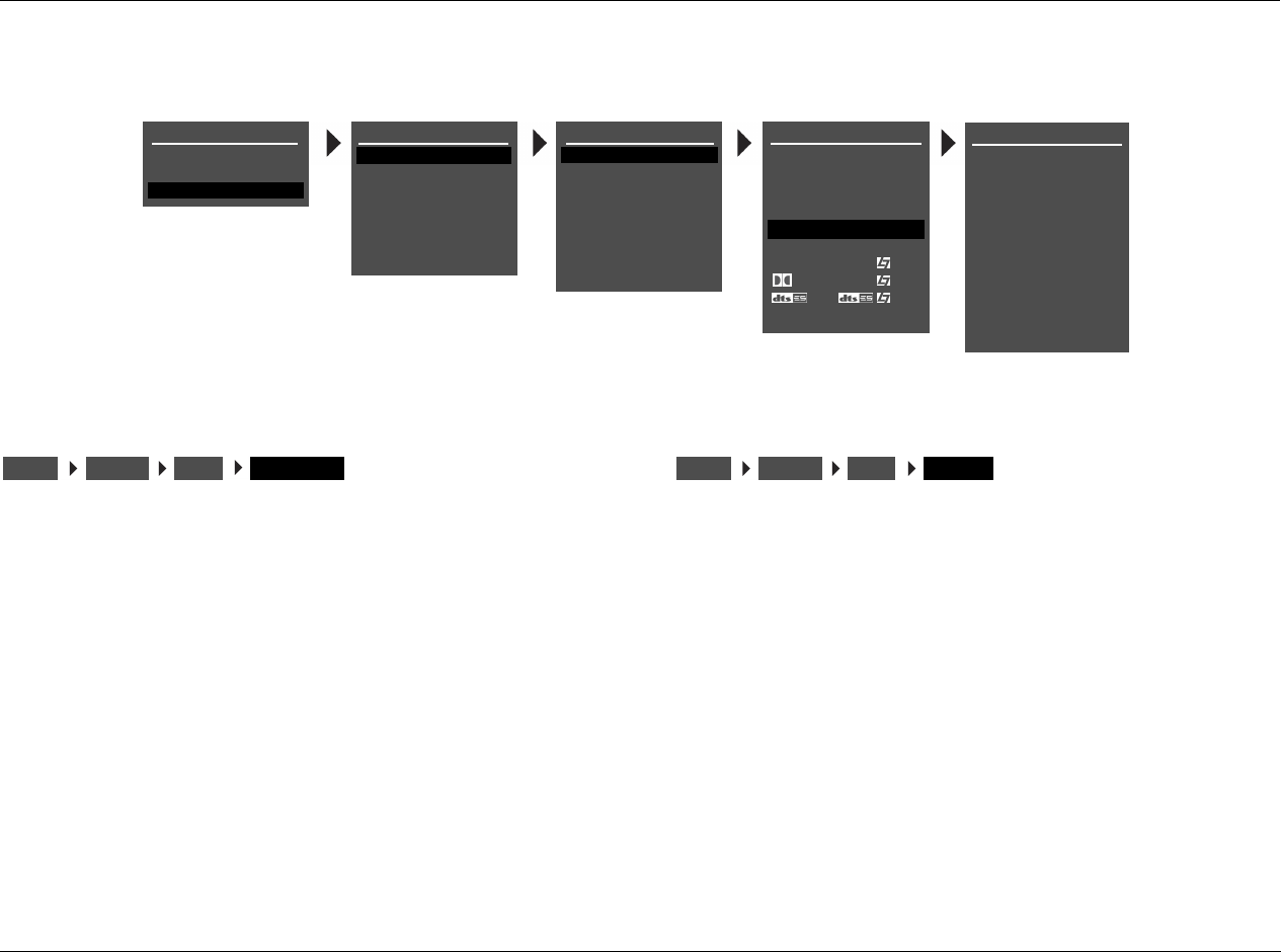
AV1 Setup
3-11
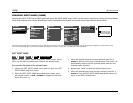
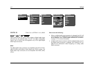
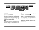
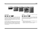
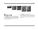
LEVEL METERS
Indicate fluctuating input levels in the front left (L) and front right
(R) channels for the selected input. These level meters are also
included on the STATUS menus, allowing them to indicate input
levels for both analog and digital audio input sources. However,
ANLG IN LVL menu input level adjustments only affect 2-channel
analog audio input sources.
Level meters appear in combinations of green, yellow and red
when the on-screen display is configured for a blue screen back-
ground. Green indicates low levels; yellow indicates normal levels;
and red indicates the onset of overload. Level meters appear in
white when the on-screen display is not configured for a blue-
screen background.
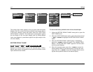
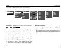
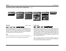
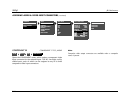
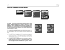
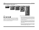
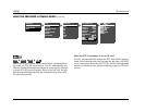
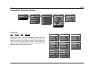
VIDEO IN COMPOSITE-1 TO 5, S-VIDEO-1 TO 5, NONE
Opens the VIDEO IN menu, which assigns a composite or S-video
input connector for the selected input. The AV1 has eight config-
urable inputs, each of which can be assigned to any of its five com-
posite or five S-video input connectors.
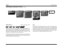
Note:
• Composite video output connectors are available when a com-
posite or S-video source is present.
• Component video output connectors are available when a
component, composite or S-video source is present.
DVD1 VIDEO IN
COMPOSITE-1
MAIN MENU
MODE ADJUST
AUDIO CONTROLS
SETUP
SETUP
INPUTS
SPEAKERS
REAR PANEL CONFIG
DISPLAYS
VOLUME CONTROLS
TRIGGER
LOCK OPTIONS
INPUT SETUP
DVD1
DVD2
SAT
VCR
TV
CD
TUNER
AUX
COMPOSITE-2
COMPOSITE-3
COMPOSITE-4
COMPOSITE-5
S-VIDEO-1
S-VIDEO-2
S-VIDEO-3
S-VIDEO-4
S-VIDEO-5
NONE
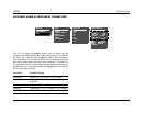
DVD1 INPUT SETUP
NAME
DIGITAL IN
ANALOG IN
VIDEO IN
COMPONENT IN
2-CH
ADVANCED
D
DVD1
COAX-1
NONE
AUTO
S-VIDEO-1
1
FILM
5.1 FILM
FILM
ANLG IN LVL
INPUTSSETUP
DVD1
ANGL IN LVL
INPUTSSETUP
DVD1
VIDEO IN


