


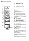
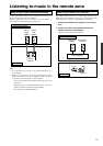
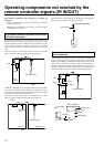

18
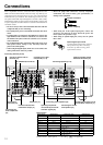
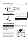
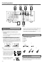
Connecting a subwoofer
Use the PRE OUT SUBWOOFER jack to connect a subwoofer with
a built-in power amplifier. If your subwoofer does not have a built-in
amplifier, connect an amplifier to the PRE OUT SUBWOOFER jack
and the subwoofer to the amplifier.
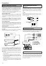
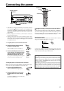
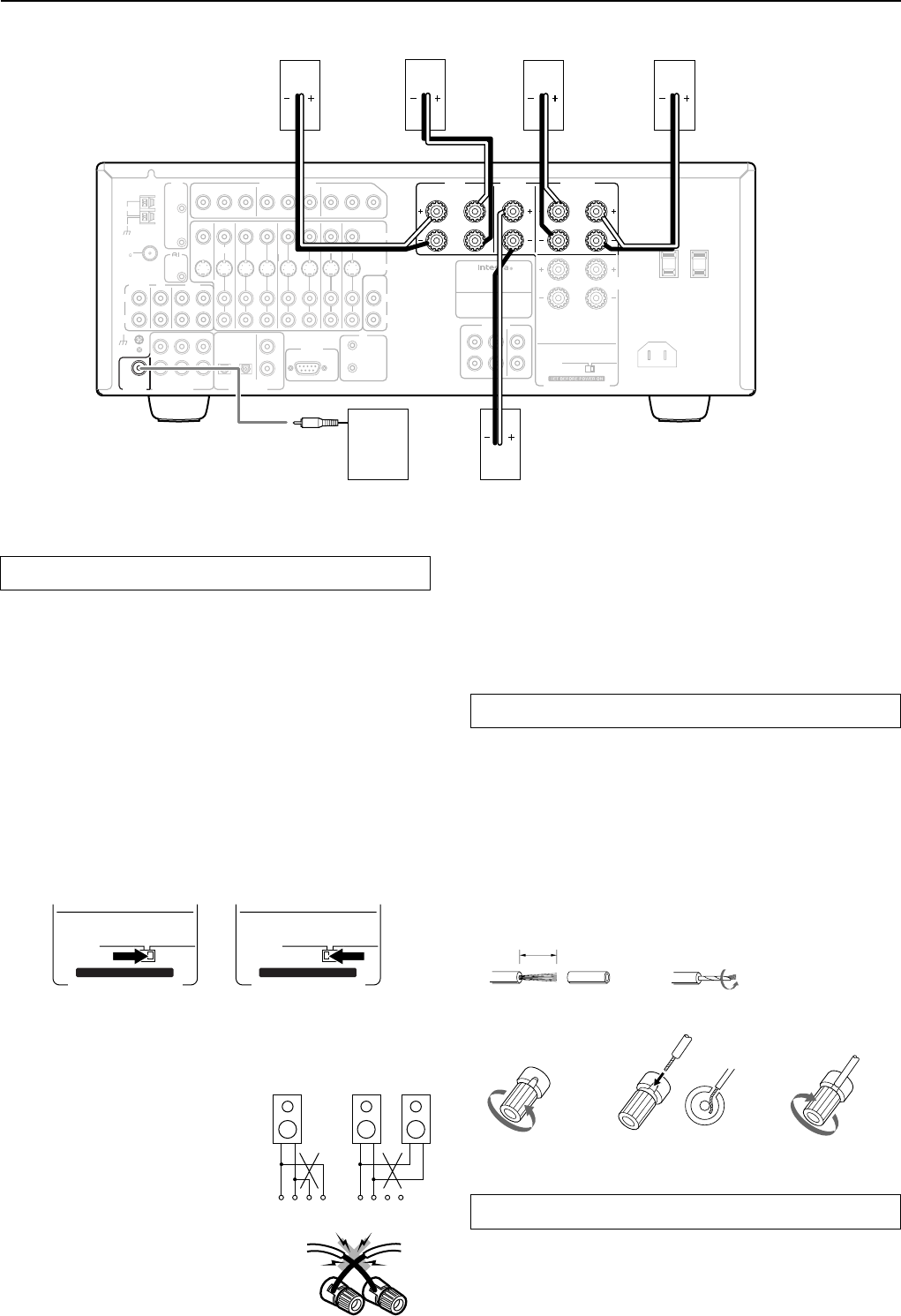
Connecting the speaker cable
1. Strip away 5/8 inch of wire insulation.
2. Twist wire ends very tight.
3. Unscrew
4. Insert wire
5. Screw
5/8"
12
34 5
Connecting speakers
• Be sure to connect the positive and negative cables for the
speakers properly. If they are mixed up, the left and right signals
will be reversed and the audio will sound unnatural.
• Do not connect more than one speaker cable to one speaker
terminal. Doing so may damage the DTR-6.2.
Connecting speakers
Make the connections while referring to the explanations on the next
page.
1. Check the impedance of the speakers you are
connecting.
The DTR-6.2 requires speakers with an impedance of 4 Ω or
greater. Connecting speakers with an impedance of less than 4 Ω
may damage the DTR-6.2.
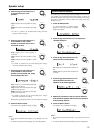
2. Set the IMPEDANCE SELECTOR switch according to
the impedance of the speakers being connected.
If all speakers have an impedance of 6 Ω or greater, slide the
IMPEDANCE SELECTOR switch to the left (6 OHMS MIN./
SPEAKER). If one or more speakers have an impedance of less
than 6 Ω, slide the IMPEDANCE SELECTOR switch to the
right (4 OHMS MIN./SPEAKER).
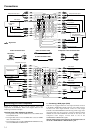
• When you are using only one speaker
or when you wish to listen to
monaural (mono) sound, a single
speaker should never be connected in
parallel to both the right and left-
channel terminals simultaneously.
• To prevent damage to circuitry,
never short-circuit the positive (+)
and negative (–) speaker wire.
Notes:
• The power to the DTR-6.2 must not be turned on when changing
the IMPEDANCE SELECTOR setting.
+ ––++––+
RL RL
NO!
6 OHMS
MIN.
/
SPEAKER
4 OHMS
MIN.
/
SPEAKER
IMPEDANCE SELECTOR
SET BEFORE POWER ON
6 OHMS
MIN.
/
SPEAKER
4 OHMS
MIN.
/
SPEAKER
IMPEDANCE SELECTOR
SET BEFORE POWER ON
4 Ω or above/speaker 6 Ω or above/speaker
NO!
IN
R
L
AC
OUTLETS
AC 120
V 60
Hz
SWITCHED
TOTAL 120
W
1
A MAX.
ZONE 2
SPEAKERS
AC INLET
R
L
CAUTION
:
SEE INSTRUCTION MANUAL
FOR CORRECT SETTING.
6 OHMS
MIN.
/
SPEAKER
4 OHMS
MIN.
/
SPEAKER
IMPEDANCE SELECTOR
FRONT SURR
L
R
1
2
PRE
OUT
CENTER
MODEL NO. DTR-6.2
FRONT
SPEAKERS
CENTER
SPEAKER
SURROUND
SPEAKERS
R
L
R
L
AV RECEIVER
P
B
P
R
Y
REMOTE
CONTROL
INPUT 1
INPUT 2OUTPUT
75
AM
ANTENNA
P
B
P
R
Y
P
B
P
R
Y
COMPONENT
VIDEO
L
VIDEO
1
VIDEO
2
DVD
VIDEO
4
IN
OUT
IN
OUT
IN
IN
IN
MONITOR
OUT
VIDEO
3
ZONE 2
PRE OUT
A
B
12
V
TRIGGER
VIDEO
S
VIDEO
CENTER
SUB
WOOFER
FRONT
SURR
SUBWOOFER
OPTICAL
COAXIAL
1
2
12
PRE OUT
MULTI
CHANNEL INPUT
DIGITAL
INPUT
L
R
OUT
IN
PHONO
TAPE
CD
GND
R
IN
IR
RS
232
L
R
OUT
FM
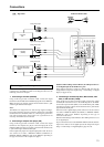
Front left
speaker
Front right
speaker
Surround left
speaker
Surround right
speaker
Center
speaker
Subwoofer