14
IN
PB
PR
Y
INPUT 1
INPUT 2OUTPUT
PB
PR
Y
P
B
PR
Y
COMPONENT
VIDEO
L
VIDEO
1
VIDEO
2
DVD
VIDEO
4
IN
OUT
IN
OUT
IN
IN
IN
MONITOR
OUT
VIDEO
3
ZONE 2
PRE OUT
VIDEO
S
VIDEO
CENTER
SUB
WOOFER
OPTICAL
COAXIAL
1
2
12
T
DIGITAL
INPUT
IN
APE
R
IR
RS
232
OUT
8. TV monitor or Projector
(MONITOR OUT)
5. VCR
(VIDEO 2)
Component video input
Video input
Video input
Video output
S video input
S video input
S video output
Analog audio output
Analog audio input
Analog audio output
Analog audio output
L (White)
L (White)
R (Red)
Video output
Video output
S video output
S video output
Digital audio output (optical)
L (White)
R (Red)
L (White)
R (Red)
R (Red)
C
R
/P
R
C
B
/P
B
Y
9. Settop box or
Video camera, etc.
(VIDEO 4)
6. Satellite tuner or TV
(VIDEO 3)
IN
PB
PR
Y
INPUT 1
INPUT 2OUTPUT
PB
PR
Y
P
B
PR
Y
COMPONENT
VIDEO
L
VIDEO
1
VIDEO
2
DVD
VIDEO
4
IN
OUT
IN
OUT
IN
IN
IN
MONITOR
OUT
VIDEO
3
ZONE 2
PRE OUT
VIDEO
S
VIDEO
CENTER
SUB
WOOFER
OPTICAL
COAXIAL
1
2
12
T
DIGITAL
INPUT
IN
APE
R
IN
IR
RS
232
OUT
4. DVD player
(DVD)
7. DVD recorder or
other digital video
recording device (VIDEO 1)
Component video output Component video output
Video output
S video output
Analog audio output
Video output
Video input
S video output
S video input
Analog audio output
Analog audio input
Digital audio output (Coaxial)
Digital audio output
(Coaxial)
L (White)
R (Red)
L (White)
S video
V
R (Red)
L (White)
R (Red)
C
R
/P
R
C
B
/P
B
Y
C
R
/P
R
C
B
/P
B
Y
Connections
: Signal flow
Audio connection cable
Left (White)
Right (Red)
L
R
Video connection cable
S video connection cable
Component video connection cable
C
R
/P
R
C
B
/P
B
Y
C
R
/P
R
C
B
/P
B
Y
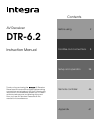
Connecting your video components
Below is an example of how you can connect your video
components to the DTR-6.2. Refer to the diagram above for the
following connection examples.
The flow of the video signals is as follows:
• The signal that comes in from VIDEO IN is sent to VIDEO OUT
and S VIDEO OUT.
• The signal that comes in from S VIDEO IN is sent to S VIDEO
OUT and VIDEO OUT.
• The signal that comes in from COMPONENT VIDEO IN is only
sent to COMPONENT VIDEO OUT.
4. Connecting a DVD player (DVD)
If the device is equipped with an S video output terminal, connect it
to the DVD S VIDEO IN terminal with an S video cable. If it does
not have an S video output terminal, connect its video output
terminal to the DVD VIDEO IN terminal using an RCA-type video
connection cable. You do not need to connect to both the DVD S
VIDEO IN and DVD VIDEO IN terminals. If the device has
component video outputs, connect them to one of the
COMPONENT VIDEO INPUT jacks.
With the initial settings of the DTR-6.2, the DVD input source is
set for the COMPONENT VIDEO INPUT 1 jack.