


ADJUSTMENT PROCEDURE
6-10
November 1998
Part No. 001-7600-001
6.8 RECEIVER ADJUSTMENTS (UHF MODELS)
6.8.1 BANDPASS FILTER ADJUST
1. Select the channel on the low end of the band (Test
Ch. 1).
2. Connect an RF signal generator to the antenna jack.
Set the output for the channel frequency at a level of
3.2 µV (–97 dBm), modulated with 1 kHz at the
following deviation:
Wideband (25 kHz) Models - 3.5 kHz
Narrowband (12.5 kHz) Models - 1.75 kHz
3. Adjust the filters automatically or manually as
follows:
Automatic Adjustment Method 1
(Adjusts all filters)
a. Select “BPF T1” on the screen and adjust for “0”.
Repeat for T2 – T4. Reselect “BPF T1”.
b. Press the F9 key and all filters are automatically
adjusted for peak levels.
Automatic Adjustment Method 2
(Adjusts only one filter at a time)
a. Select “BPF T1” and press F8 to automatically
adjust it for a peak level.
b. Repeat for the other three filters.
Manual Adjustment
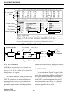
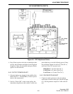
a. Connect a SINAD meter with a 4-ohm load to the
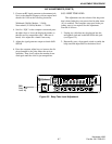
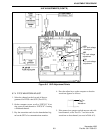
external speaker jack (see Figure 6-6).
b. Select “BPF T1” and press the adjust keys (←/
→,
PgUp/PgDn, or spacebar/backspace) to obtain
minimum distortion.
c. Repeat for the other three filters.
6.8.2 SQUELCH ADJUST
NOTE: The squelch level can also be set from the
front panel as described in Section 3.3.6.
1. Select the channel on the low end of the operating
band (Test Ch. 2). channel with LB models and the
150.050 MHz channel with HB models.
2. Connect a SINAD meter with a 4-ohm load to the
external speaker jack.
3. Connect an RF signal generator to the antenna jack.
Set it to the channel frequency with an output mod-
ulated with 1 kHz at the following deviation:
Wideband (30 kHz) Models - 3.5 kHz
Narrowband (12.5 kHz) Models - 1.75 kHz
4. Scroll to “SQL” on the computer screen and press
the adjust keys to lower the displayed number so
that the receiver unsquelches (the 1 kHz tone is
heard). Also adjust the volume if necessary.
5. Adjust the signal generator output to obtain 8 dB
SINAD.
6. Press the computer adjust keys to increase the dis-
played number to the point where the receiver
squelches. Then slowly adjust the number down-
ward again until the receiver just unsquelches.
6.8.3 BEEP TONE LEVEL
This adjustment sets the volume of the beep tone
that is heard when keys are pressed and at other times
(if it is enabled). The computer setup used in the pre-
ceding steps is not required for this adjustment. Pro-
ceed as follows:
1. Unplug any cable that may be plugged into the
microphone jack and locate R60 inside this jack.
(see Figure 6-5).
2. Repeatedly press a front panel switch to enable the
beep tone and adjust R60 for the desired level.
UHF ADJUSTMENTS (CONT’D)