


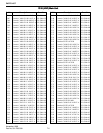
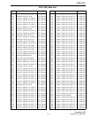
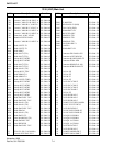
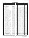

ADJUSTMENT PROCEDURE
6-8
November 1998
Part No. 001-7600-001
UHF ADJUSTMENTS
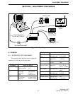
NOTE: Perform the preliminary setup described in
Section 6.2 before proceeding with these adjustments.
6.6 PLL ADJUSTMENT (UHF MODELS)
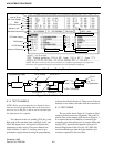
1. Remove the bottom cover by removing four screws.
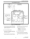
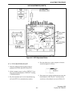
Connect a DC voltmeter to check point CP1 shown
in Figure 6-6.
2. Select the channel at the low end of the band
(Test Ch. 1). This is done by pressing the ↑ ↓ arrow
keys to highlight “Memory CH” and then pressing
the adjust keys (←/
→,
PgUp/PgDn, or spacebar/
backspace) to select the channel.
3. In the receive mode, the meter reading should be 1.5
volts. If this voltage is significantly different, adjust
L23 (it may be necessary to remove the shield).
4. Key the transmitter using the switch on the test
cable and the meter reading also should be 1.5 volts.
If this voltage is significantly different, adjust L26.
5. Unkey the transmitter and select the channel on the
high end of the band (Test Ch. 2). The meter reading
in the receive and transmit modes should be 3.5 –
5.5 volts. Replace the bottom cover.
6.7 TRANSMITTER ADJUSTMENTS (UHF
MODELS)
6.7.1 REFERENCE FREQUENCY
1. Select the low power channel on the high end of the
band (Test Ch. 2).
2. Scroll down to “TXF SET” on the screen and press
(Enter). Monitor the transmit signal with a fre-
quency counter and key the transmitter using the
test cable switch.
3. Adjust for the displayed frequency by pressing the
computer adjust keys. Unkey the transmitter.
4. Press (Enter) again to select the second adjust chan-
nel. Key the transmitter and adjust for the displayed
frequency. Unkey the transmitter and press (Enter)
again to exit this function.
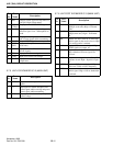
6.7.2 OUTPUT POWER ADJUST
1. Select the high power channel at the low end of the
band (Test Ch. 3). Connect a power meter to the
antenna jack.
2. Scroll to “Power (Hi)” on the screen and key the
transmitter using the test cable switch. Use the com-
puter adjust keys to set the following power. Unkey
the transmitter. Repeat for the Low2 (Test Ch. 4)
and Low1 (Test Ch. 5) power levels.
High Power = 35 watts
Low2 Power = 20 watts
Low1 Power = 3.5 watts
6.7.3 FM DEVIATION ADJUST
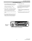
1. Connect an audio generator to the microphone
audio input of the test cable (pin 5 shown in Figure
6-3). Set the generator output for 1 kHz at 40 mV
rms.
2. Select the low power channel at the low end of the
band (Test Ch. 1). On the computer screen, scroll to
“MOD N” if setting narrow band deviation or
“MOD W” if setting wideband deviation.
3. Monitor the transmit deviation with a communica-
tions monitor set as follows: HPF = Off, LPF = 20
kHz, De-Emphasis = Off, Detector = (P–P)/2.
4. Key the transmitter using the test cable switch and
set the following maximum deviation by pressing
the adjust keys (←/
→,
PgUp/PgDn, or spacebar/
backspace). Unkey the transmitter.
Wideband (30 kHz) Models - 4.2 kHz
Narrow Band (12.5 kHz) Models - 2.1 kHz
5. If the transceiver operates on both narrow and wide
band channels, select Test Ch. 6 and also adjust the
deviation on that channel (see note in Table 6-2).