


2-1
November 1998
Part No. 001-7600-001
INSTALLATION AND DISASSEMBLY
SECTION 2 INSTALLATION AND DISASSEMBLY
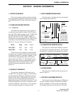
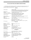
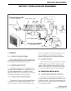
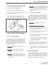
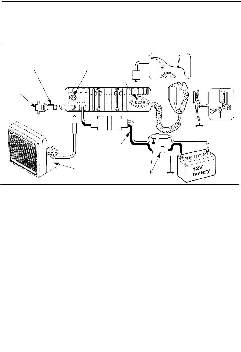
Figure 2-1 Installation Components
Optional Accessory Cable
P.N. 585-7600-027
DB-9 Female
Optional External Speaker
P.N. 250-0151-010
10-Ft. Power Cable
Red (+)
Black (–)
20A Fuses
External Spkr Jack
UHF-Type
Ant Jack
2.1 GENERAL
2.1.1 SCOPE OF INSTRUCTIONS
Since each installation is somewhat unique, the
following installation instructions are intended only as
a general guide to installing this transceiver.
2.1.2 PERFORMANCE TESTS
Although each transceiver is carefully tested at
the factory before shipment, it is good practice to ver-
ify proper operation before it is placed in service.
Important checks are receiver sensitivity and transmit-
ter frequency, deviation, and power output.
2.1.3 TRANSCEIVER PROGRAMMING
The transceiver needs to be programmed before it
is placed in service. Programming instructions are
located in Section 4. Transceivers normally contain
factory test channels and other test parameters when
they are shipped. The included labels should be
attached to the option keys to indicate the function.
2.1.4 POWER SOURCE
This transceiver must be connected to a nominal
12 VDC, negative ground vehicle electrical system
(negative battery terminal connected directly to the
chassis). If the vehicle has some other type of electri-
cal system, a suitable voltage converter is required.
2.2 TRANSCEIVER INSTALLATION
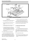
2.2.1 SELECTING MOUNTING LOCATION
This transceiver is designed for mounting in a
location within convenient reach of the operator such
as the dash, console, or floor. Since the mounting loca-
tion can affect safe operation of the vehicle, observe
the following precautions: