INSTALLATION AND DISASSEMBLY
2-4
November 1998
Part No. 001-7600-001
2.6 TRANSCEIVER DISASSEMBLY
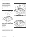
Removing Bottom Cover and Front Panel
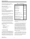
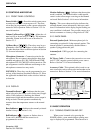
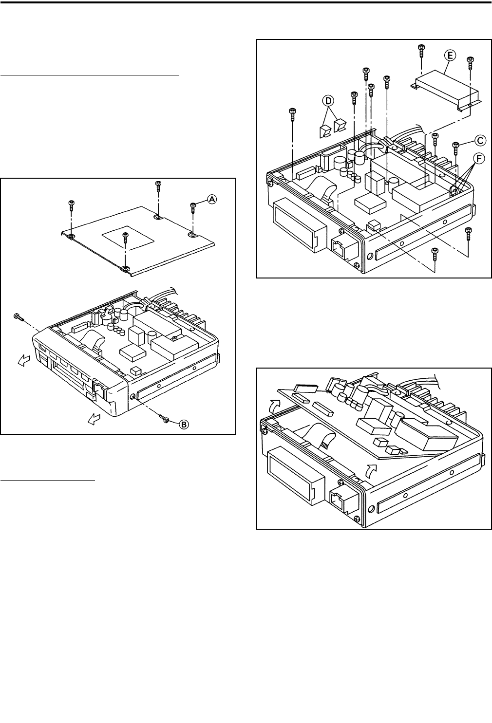
1. Remove the bottom cover by removing four screws
(A) as shown in Figure 2-4.
2. Remove the front panel by removing two screws
(B).
Figure 2-4 Cover and Front Panel Removal
Removing PC Board
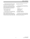
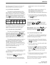
3. Remove ten screws (C) and two clips (D) as shown
in Figure 2-5.
4. Remove shield (E).
5. Unsolder the antenna connector at three points (F).
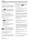
6. Lift the front of the PC board assembly as shown in
Figure 2-6 and pull it out.
Figure 2-5 PC Board Screws
Figure 2-6 Removing PC Board


