


PROGRAMMING
4-6
November 1998
Part No. 001-7600-001
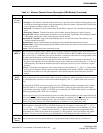
RF PWR Programs the RF power output for the channel (High, Low1, Low2). This setting can be temporarily or perma-
nently overridden by the HIGH, LOW1, or LOW2 power option switch if it is programmed (see Table 4-2).
Lockout Transmit Disable On Busy. The following conditions can be programmed:
Off - No restrictions; the transmitter can be keyed even while receiving a signal.
Busy - Transmitting is inhibited if the channel is busy (carrier present).
Repeater 1 - Transmission is permitted only when (1) receiving a signal on the programmed Call Guard tone or
code (CTCSS/ DCTS) or (2) when no carrier is being detected.
Repeater 2 - Transmission is permitted when (1) receiving any Call Guard tone or code (CTCSS/DCTS) or (2)
when no carrier is being detected.
NOTE: If an attempt is made to transmit in a lockout condition, transmitting is inhibited for the “Lockout
Penalty Time” programmed on Common screen (see Table 4-7).
Scan Assigns the channel to up to five scan lists and also programs if the scan list status can be changed by the scan
list programming key (TAG). Press the spacebar to enter or delete all lists or press 1-5 to toggle the status of a
list. Press the backspace key to toggle the inhibit status. Scan list programming is inhibited when parentheses
are displayed around the numbers (or underline characters).
Auto Reset If PWR ON Scan is enabled in the Scan screen (see Table 4-5), this selects the time delay before scanning
resumes after a call is complete (the signal disappears) or a key is pressed. Either Timer A or Timer B can be
selected. These timers are programmed in the Common Screen (see Table 4-7). Auto reset can be turned off by
setting the timer to “Off” (0).
2-Tone Enables 2-tone operation on the channel and specifies the 2-tone code used. The 2-tone codes are programmed
in the 2-Tone Code Ch screen (see Table 4-6). This requires the optional 2/5-tone module.
Log On/Off Specifies if the DTMF ID code is transmitted when the PTT switch is pressed and released. The DTMF code is
specified on the Log/ID line of the DTMF Autodial screen (Table 4-3). In the Common screen, if “TOT Timer
ID Out” is “Yes”, this ID is also transmitted just before the transmitter is disabled by the time-out timer. The
following conditions can be programmed:
OFF (blank) - No ID code is transmitted.
Log In - The ID code is transmitted when the PTT switch is pressed.
Log Off - The ID code is transmitted when the PTT switch is released.
Both - The ID code is transmitted when the PTT switch is pressed and again when it is released.
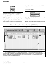
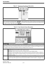
Table 4-1 Memory Channel Screen Description (LMR Models) (Continued)
Parameter Description