


INSTALLATION AND DISASSEMBLY
2-2
November 1998
Part No. 001-7600-001
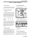
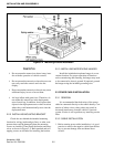
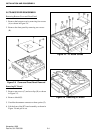
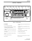
Figure 2-2 Mounting Bracket Installation
WARNING
•
Do not mount the transceiver where it may inter-
fere with the operation of vehicle controls.
•
Do not mount the transceiver where the user can-
not easily reach the controls and view the
display.
•
Do not mount the transceiver where it may cause
additional injury in case of an accident.
•
Air bags inflate with great force. Therefore, do
not mount this transceiver in the deployment
area of an air bag. In addition, do not place other
objects in the deployment area or other locations
where they could unintentionally move into the
deployment area.
2.2.2 INSTALLING MOUNTING BRACKET
Check the area behind the intended mounting
location for wiring, brake and gas lines, or other com-
ponents that could be damaged when the mounting
screws are installed. Then install the bracket and trans-
ceiver as shown in Figure 2-2. Both standard and self-
tapping screws are included for installing the bracket.
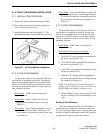
2.2.3 INSTALLING MICROPHONE HANGER
Install the included microphone hanger in a con-
venient location. For proper operation of functions
such as monitoring and scanning, the hanger may need
to be connected to chassis ground. If required, ground
the hanger using the included grounding wire.
2.3 POWER CABLE INSTALLATION
2.3.1 GENERAL
It is recommended that both wires of the power
cable be connected directly to the vehicle battery. Con-
nection of either wire to other points may result in
increased interference from the vehicle’s electrical
system. If noise is still a problem, try installing a noise
filter.
2.3.2 CABLE INSTALLATION
1. Before starting power cable installation, it is good
practice to remove the negative cable from the bat-
tery to prevent damage from accidental short
circuits.