


ADJUSTMENT PROCEDURE
6-2
November 1998
Part No. 001-7600-001
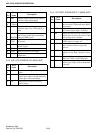
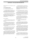
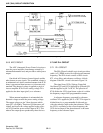
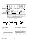
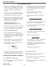
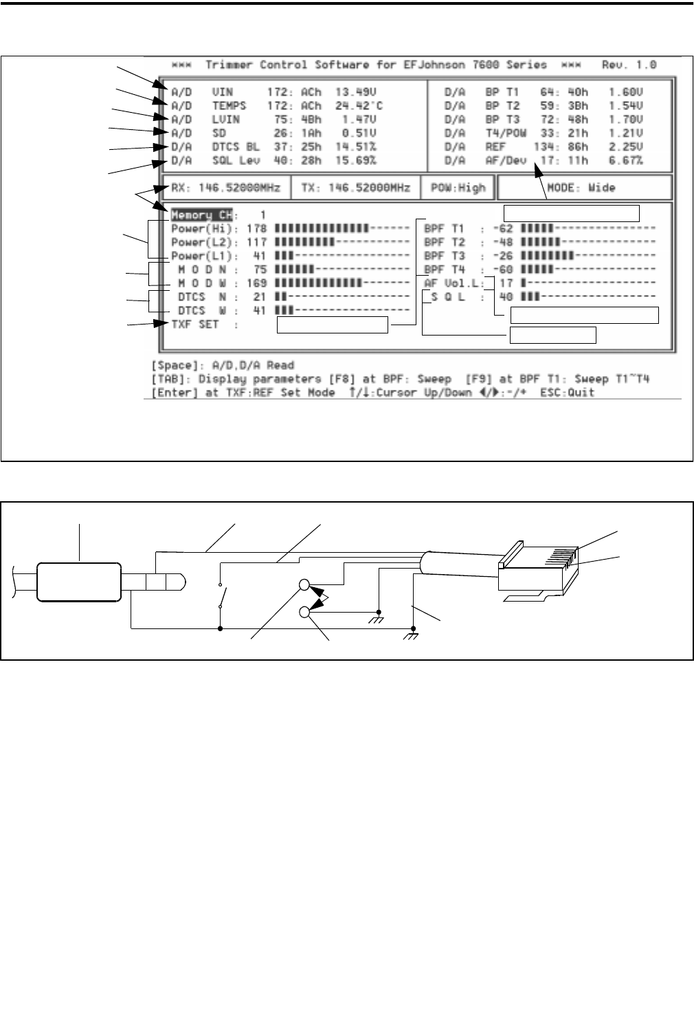
Figure 6-2 Screen Display Example
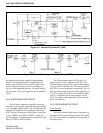
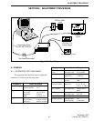
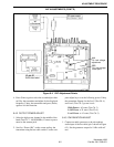
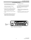
Figure 6-3 Test Cable Schematic
DTCS Bal Level
Squelch Level
Selected Channel Info
RF Power Output
FM Deviation
DTCS Balance
Reference Frequency
Supply Voltage
Internal Temp
PLL Lock Voltage
RSSI
IC5/IC12 D/A Outputs
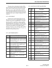
NOTE: The above values for the various settings are examples only. Because of component
tolerances, the optimum setting for each transceiver will probably be different.
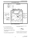
Rx Bandpass Filter
Squelch Level
Adjusts Current Vol Level
Pin 8
Pin 1
Pin 7 (Ground)
Pin 2 (Clone)
Pin 4 (PTT)
Pin 5 (MICE “+”)
Pin 6 (MIC “–”)
Programming Cable
PTT
Sw
Mic In
To Transceiver
To Computer
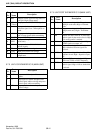
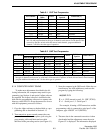
6.1.2 TEST CHANNELS
NOTE: Before programming the test channels, down-
load the current programming data in the transceiver
and save it to a disk file so that it can be reloaded after
the adjustments are complete.
Test channels at the low, middle (VHF only), and
high ends of the operating band, and High, Low1, and
Low2 RF output power are required to perform the
adjustments in this section. These test channels are
listed in Tables 6-1 and 6-2, and they must be pro-
grammed as regular channels using the programming
software described in Section 4. There are no fixed test
channels or test modes selectable with this transceiver.
6.1.3 TEST CABLE
The test cable shown Figure 6-3 in must be fabri-
cated to perform transceiver alignment. This cable is
used in place of the adapter cable shown in Figure 4-1.
It is required because in addition to connecting the
computer to the microphone jack, a transmit audio and
keying (PTT) signal must be applied to that jack. If
desired, Replication Cable, Part No. 597-2002-200,
can be modified to provide the 8-pin modular-style
connector required for this test cable.