


ADJUSTMENT PROCEDURE
6-6
November 1998
Part No. 001-7600-001
2. Select the low power channel in the middle of the
band (Test Ch. 5 - 160.050 MHz). On the computer
screen, scroll to “MOD N” if setting narrow band
deviation or “MOD W” if setting wideband
deviation.
3. Monitor the transmit deviation with a communica-
tions monitor set as follows: HPF = Off, LPF = 20
kHz, De-Emphasis = Off, Detector = (P–P)/2.
4. Key the transmitter using the test cable switch and
set the following maximum deviation by pressing
the adjust keys (←/
→,
PgUp/PgDn, or spacebar/
backspace). Unkey the transmitter.
Wideband (30 kHz) Models - 4.2 kHz
Narrow Band (12.5 kHz) Models - 2.1 kHz
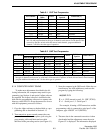
5. If the transceiver operates on both narrow and wide
band channels, select Test Ch. 7 and also adjust the
deviation on that channel (see note in Table 6-1).
6.4.4 DTCS WAVEFORM ADJUST
1. Select a channel in the middle of the band pro-
grammed for DTCS (Test Ch. 8 - 160.050 MHz). On
the computer screen, scroll to “DTCS N” if setting
a narrow band channel or “DTCS W” if setting a
wideband channel.
2. Key the transmitter and view the demodulated sig-
nal on the CRT of a communications monitor.
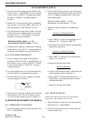
3. Press the adjust keys on the computer so that the
waveform appears as follows:
4. If the transceiver operates on both narrow and wide
band channels, select Test Ch. 8 and also set the
waveform on that channel (see note in Table 6-1).
6.5 RECEIVER ADJUSTMENTS (VHF MODELS)
6.5.1 BANDPASS FILTER ADJUST
1. Select the channel on the low end of the band (Test
Ch. 2 - 146.050 MHz).
2. Connect an RF signal generator to the antenna jack.
Set the output for the channel frequency at a level of
3.2 µV (–97 dBm), modulated with 1 kHz at the
following deviation:
Wideband (30 kHz) Models - 3.5 kHz
Narrowband (12.5 kHz) Models - 1.75 kHz
3. Adjust the filters automatically or manually as
follows:
Automatic Adjustment Method 1
(Adjusts all filters)
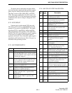
a. Select “BPF T1” on the screen and adjust for “0”.
Repeat for T2 – T4. Reselect “BPF T1”.
b. Press the F9 key and all filters are automatically
adjusted for peak levels.
Automatic Adjustment Method 2
(Adjusts only one filter at a time)
a. Select “BPF T1” and press F8 to automatically
adjust it for a peak level.
b. Repeat for the other three filters.
Manual Adjustment
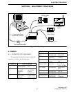
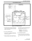
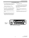
a. Connect a SINAD meter with a 4-ohm load to the
external speaker jack (see Figure 6-4).
b. Select “BPF T1” and press the adjust keys (←/
→,
PgUp/PgDn, or spacebar/backspace) to obtain
minimum distortion.
c. Repeat for the other three filters.
6.5.2 SQUELCH ADJUST
NOTE: The squelch level can also be set from the
front panel as described in Section 3.3.6.
1. Select the channel on the low end of the operating
band (Test Ch. 2 - 146.050 MHz).
2. Connect a SINAD meter with a 4-ohm load to the
external speaker jack.
Set For
Flat
Waveform
VHF ADJUSTMENTS (CONT’D)