


ADJUSTMENT PROCEDURE
6-3
November 1998
Part No. 001-7600-001
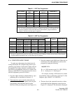
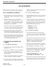
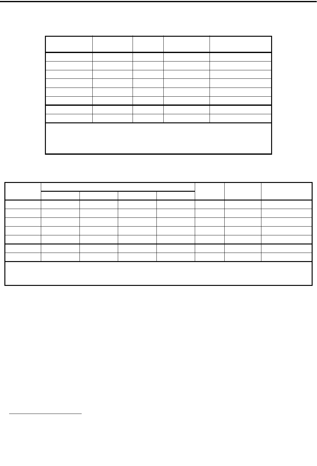
Table 6-1 VHF Test Frequencies
Test Channel
Tx/Rx Freq
(MHz)
Power
Call Guard
Squelch
Bandwidth [1]
1 174.050 Low1 None Narrow or wide
2 146.050 Low1 None Narrow or wide
3 160.050 High None Narrow or wide
4 160.050 Low2 None Narrow or wide
5 160.050 Low1 None Narrow or wide
6 160.050 Low1 007N DTCS Narrow or wide
7 [1] 160.050 Low1 None Alternate
8 [1] 160.050 Low1 007 DTCS Alternate
[1] If the transceiver operates on only narrow or wide band channels, program only chan-
nels 1-6, and program them for the type of channels used (narrow or wide band). If the
transceiver operates on both wide and narrow band channels, program additional
channels 7 and 8 for the other type of operation.
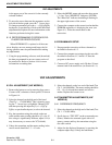
Table 6-2 UHF Test Frequencies
Test Channel
Model (see Section 1.4)
Power
Call Guard
Squelch
Bandwidth [1]
400-430 MHz 450-470 MHz 470-490 MHz 488-512 MHz
1 400.050 450.050 470.050 490.050 Low1 None Narrow or wide
2 430.050 470.050 490.050 512.050 Low1 None Narrow or wide
3 400.050 450.050 470.050 490.050 High None Narrow or wide
4 400.050 450.050 470.050 490.050 Low2 None Narrow or wide
5 400.050 450.050 470.050 490.050 Low1 007N DTCS Narrow or wide
6 [1] 400.050 450.050 470.050 490.050 Low1 None Alternate
7 [1] 400.050 450.050 470.050 490.050 Low1 007N DTCS Alternate
[1] If the transceiver operates on only narrow or wide band channels, program only channels 1-5, and program them for
the type of channels used (narrow or wide band). If the transceiver operates on both wide and narrow band channels,
program additional channels 6 and 7 for the other type of operation.
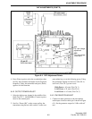
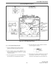
6.1.4 COMPUTER-AIDED TUNING
To make most adjustments described in the fol-
lowing information, the computer setup used for pro-
gramming (see Section 4) and special Adjust software
are required. The Adjust
software is included on the
disk with the programming software in a separate sub-
directory called ADJ. To set up the transceiver for use
with this equipment, proceed as follows:
1. Copy the Adjust software to the hard disk or a pro-
gramming disk as described in Section 4.1.3
2. Turn transceiver power on
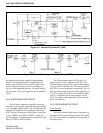
and connect the com-
puter to the transceiver microphone jack using the
programming cable and fabricated test cable
described in the preceding section (see Figure 6-1).
3. Start the computer in the DOS mode. Make the cur-
rent directory the ADJ subdirectory and start the
program by typing the following:
ADJUST /X /Y
X
= A - VHF (normal crystal), B - UHF (TCXO)
Y
= 1 - Serial port 1, 2 - Serial port 2
For example, if tuning a VHF transceiver and the
programming cable is connected to serial port 2 of the
computer, type ADJUST /A /2 (ENTER).
4. The tune data in the connected transceiver is then
downloaded and the adjustment screen shown in
Figure 6-2 is displayed. The information displayed