


ADJUSTMENT PROCEDURE
6-5
November 1998
Part No. 001-7600-001
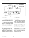
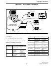
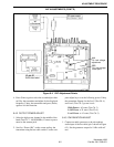
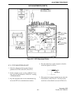
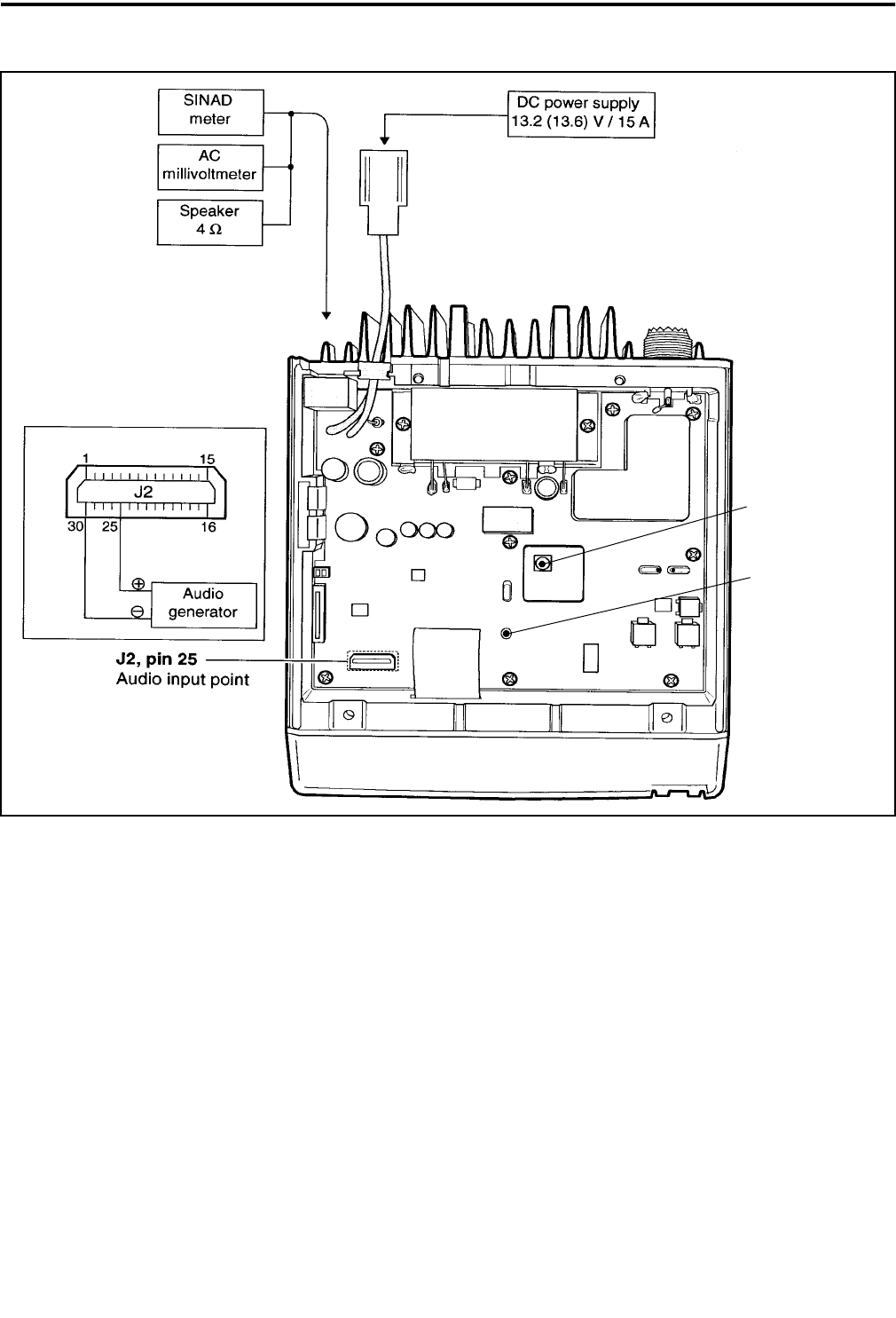
Figure 6-4 VHF Adjustment Points
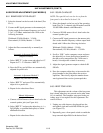
4. Press (Enter) again to select the second adjust chan-
nel. Key the transmitter and adjust for the displayed
frequency. Unkey the transmitter and press (Enter)
again to exit this function.
6.4.2 OUTPUT POWER ADJUST
1. Select the high power channel in the middle of the
band (Test Ch. 3 - 160.050 MHz). Connect a power
meter to the antenna jack.
2. Scroll to “Power (Hi)” on the screen and key the
transmitter using the test cable switch. Use the com-
puter adjust keys to set the following power. Unkey
the transmitter. Repeat for the Low2 (Test Ch. 4)
and Low1 (Test Ch. 5) power levels.
High Power = 45 watts (Test Ch. 3)
Low2 Power = 25 watts (Test Ch. 4)
Low1 Power = 4.5 watts (Test Ch. 5)
6.4.3 FM DEVIATION ADJUST
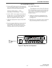
1. Connect an audio generator to the microphone
audio input of the test cable (pin 5 shown in Figure
6-3). Set the generator output for 1 kHz at 40 mV
rms.
L14
PLL lock voltage
adjustment
CP1
PLL lock voltage
check point
VHF ADJUSTMENTS (CONT’D)