


Using the DP570 Features Emulator Bypass
Dolby
®
DP570 Multichannel Audio Tool User’s Manual 39
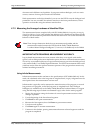
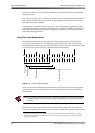
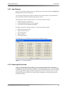
Table 4‐6describestheelectricalcharacteristics.
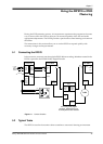
4.14 Emulator Bypass
WhenyouenableEmulatorBypass,thefront‐panelEscbuttonisilluminated.Inthis
mode,theonlysettingsthataffecttheoutputaretheroutersettings.Monitoringoptions
arelimitedtoprogramselection.Ifyouareusingthe
Lt/Rt Input,thatsignalissent,without
decoding,totheLeftandRightemulatoroutputs.Bassmanagementremainsactive.
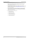
4.15 Solo Input Mode
TheDP570providesatwo‐channelanaloginputthatcanberoutedtotheanalogoutputs.
Thisinputiscalled
Solobecausethefeatureprovidesawaytorouteastandardsignalfrom
amixer(suchasthemixer’ssolobusoutput)intothemonitorchain.Thefeaturecanalso
beusefulasageneral‐purposeanalogbypass.
SoloInputmodebypassesthedigitalaudioinputs,andonlythesoloinputs
fromthe
Analog I/O connectoronthebackpanelroutetotheLeftand Rightoutputs.IftheMono
speakeroutputisselected,theinputsignalsaresummedandfedtothe
Monooutput.
The
SoloinputisavailableonlybydrivingtheSoloControllineontheGPI/Oport.TheSolo
Controlline(pin6)islevel‐triggeredandisactiveinthehighstate.Thestatusofthe
Solo
inputdisplaysonthefront‐panel
SoloLEDandisindicatedontheSoloTallyline(pin5)
onthe
GPI/Oport.
4.16 Unity Gain Mode
UnityGainmodedefeatstheaudibleeffectsofdialoguenormalizationwhileallowingthe
dialnormvaluetobeusedinchoosingdynamicrangecontrolsettings.Itisvaluablewhen
theemulatoroutputsoftheDP570arereturnedtotheconsoleforuseasmonitorinputs.
UnityGainmodeisenabledbydefault.
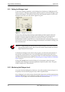
ToturnUnityGainmodeoff:
1. ClickSetupintheMainwindowtoopentheSetupwindow.
2. UnchecktheUnityGainModeboxontheleftsidenearthebottom.
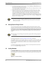
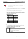
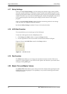
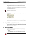
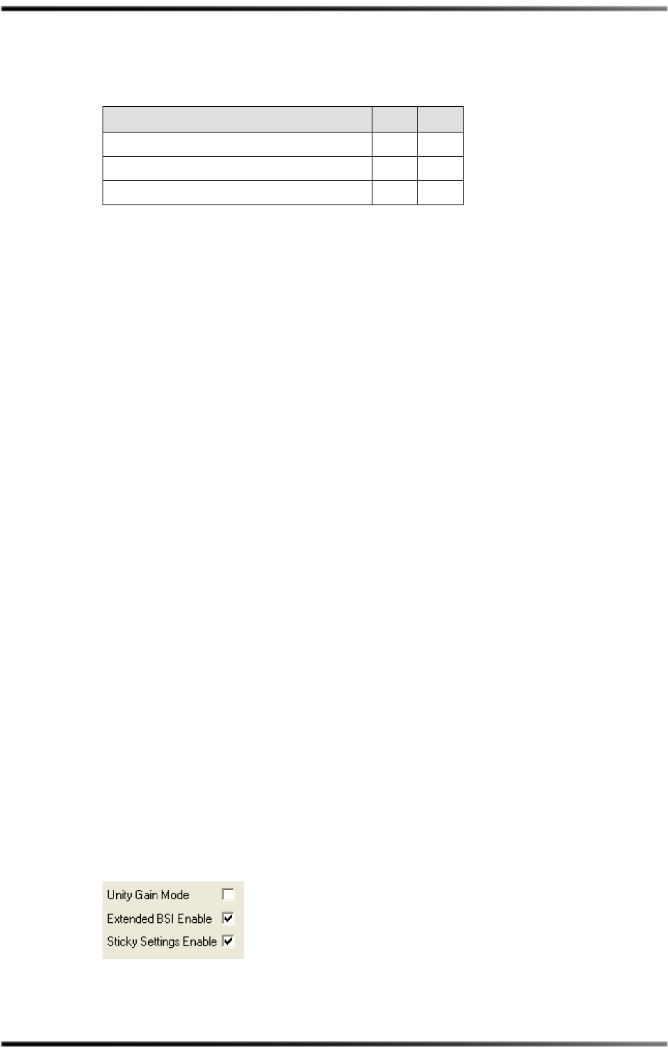
Figure 4‐8showsadetailoftheUnityGainModeboxontheSetupwindow.
Figure 4-8 Unity Gain Mode Box
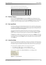
Table 4-6 Shaft Decoder Signal Electrical Characteristics
Characteristic Min Max
VT+Positive‐goinginputthresholdvoltage 1.2V2.1V
VT–Negative‐goinginputthresholdvoltage 0 .5V1.4V
VHHysteresisvoltage 0.4V1.5V