


18 Dolby
®
DP570 Multichannel Audio Tool User’s Manual
Controlling the DP570 Using the Setup Menu
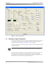
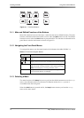
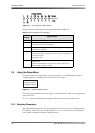
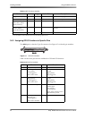
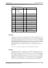
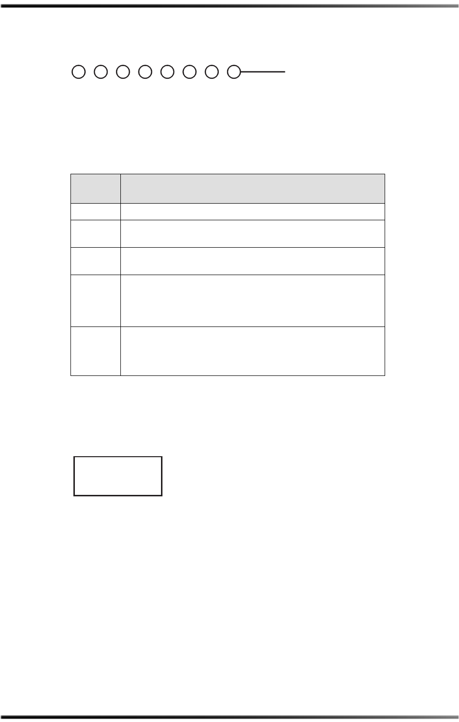
Figure 3-5 Channel Activity LED Indicators
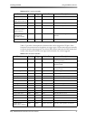
ChannelActivityLEDindicator meaningsaredetailedinTable 3‐4.
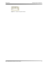
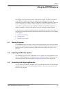
3.5 Using the Setup Menu
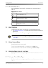
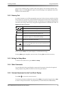
TheinitialscreenofthesetupmenuisshowninFigure 3‐6.Adetailedmapofallthe
availableoptionsisavailableinFront‐PanelMenusonpage 75.
Figure 3-6 Initial Setup Menu Screen
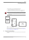
UsethenavigationbuttonsshowninFigure 3‐2anddescribedinTable 3‐1tonavigatethe
Setupmenutree.
TheSetupmenuhasadditionalnavigationroutinesnotusedonthestatusmenu.
3.5.1 Selecting Parameters
Manyparametersettingshavealistofoptionsfromwhichtochooseone.Dialoguelevel,
forexample,canbesettoanynumberbetween–1and–31.Inthesecases,theselectedor
activeoptionisdisplayedwithoutaflashingcursor.
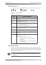
Table 3-4 Channel Activity LED Indications
LED
Display
Signal Status
YELLOW Peaksignallevelislessthan–60dBFS;ornoissignalpresent.
GREEN Peaksignallevelisgreaterthan–60dBFSandlessthan–0.1dBFS;
asignalispresentandnotclipping.
RED Peaksignallevelisgreaterthan–0.1dBFS;asignalisclipping,
interventionisrequired.
Blinking
YELLOW
Input:Channel
enabledbutnotlocked;thechannelispresentin
theselectedprogramconfiguration,butthereisnoclocksignal
presentattheinput.
Output:Notused.
Off
Input:ChannelisnotusedintheselectedDolby
®
Eprogram
configuration.
Output:Channeldisabledbydownmix,speakerselection,or
Channelmodeparametersetting.
2
Rt
3 4
1
Lt
6 7 8
5
Input
Channel Activity
Rs Bs
R C
SW
LFE
Ls
L
Output
DP570 Unit Setup
Program Select