


22 Dolby
®
DP570 Multichannel Audio Tool User’s Manual
Controlling the DP570 Using the GPI/O Connector
3.6.2 Assigning GPI/O Functions to Specific Pins
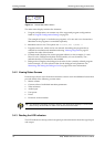
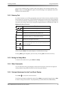
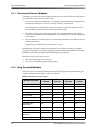
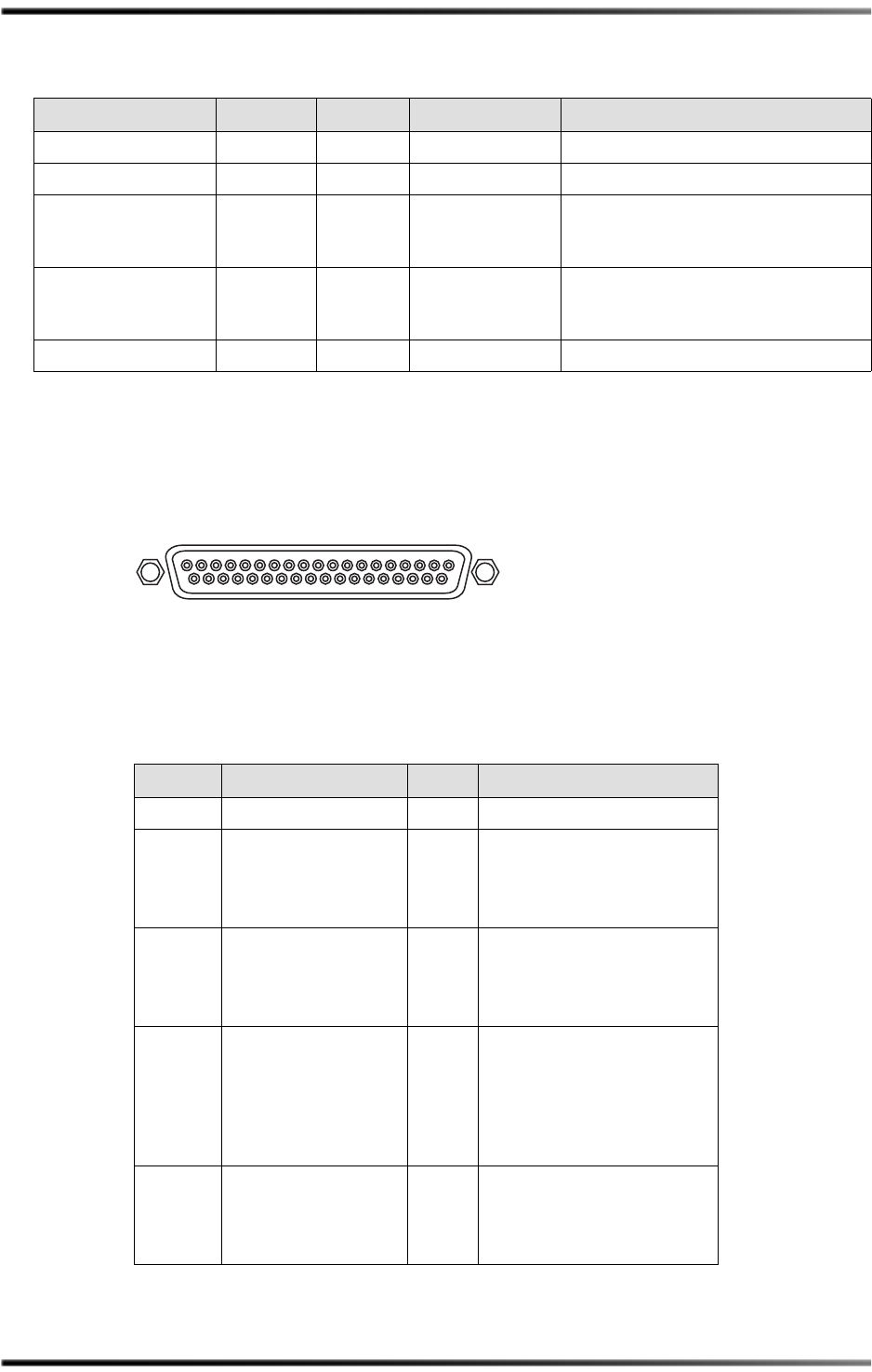
TheGPI/Oportisafemale37‐pinD‐connector.SeeFigure 3‐7toidentifypinnumbers.
Figure 3-7 GPI/O Pin Numbers
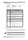
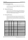
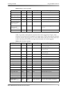
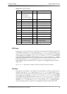
Table 3‐8showsthepinsthatareavailableforGPOandGPIfunctions.
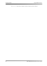
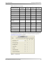
ProgramSelect(1–8) Either Either Enabled Indicateswhichprogramisselected.
PresetSelect(1–32) Either Either Enabled Indicateswhichpresetisselected.
DownmixMode
(Full,Stereo,Mono,
Phant,3‐Stereo)
Either Either Enabled Indicateswhichmodeisselected.
DynamicRange
ControlMode
(Line,RF,Custom)
Either Either Enabled Indicateswhichcompressionmodeis
selected.
ReferenceLevel
a
Either Level 0dB IndicatesMasterVolume=0dB.
a.NotavailableinunitswithouttheCat.No.548AnalogOptionCard.
Table 3-8 GPI/O Pins Available
Pin Function Pin Function
1+5V(150mA)
2Faultoutput
Lowpolarity
Level‐triggered
Activestate:Fault
20 VolumeControlShaftEncoder
Ainput
Highpolarity
Edge‐triggered
3Erroroutput
Highpolarity
Level‐triggered
Activestate:Error
21 VolumeControlShaftEncoder
Binput
Highpolarity
Edge‐triggered
4User‐definedoutput 22 VolumeControlShaftEncoder
presentinput
Lowpolarity
Level‐triggered
Activestate:VolumeControl
ShaftEncoder
present
5
Solotallyoutput
a
Highpolarity
Level‐triggered
Activestate:Enabled
23 User‐definedinput
Table 3-7 GPI Functions Available
Function Polarity Trigger Active State Description
GP I/O
1
19
37 20