


Measurement Process
Measurement Setup and Control
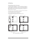
When the VT1433B makes a measurement, the measurement itself consists of two
phases: the measurement initialization and the measurement loop. Each of these
phases consists of several states, through which the measurement progresses.
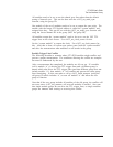
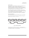
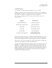
The transition from one state to the next is tied to a transition in the Sync/Trigger
line (one of the TTL trigger lines on the VXI back plane). A state (such as Idle)
begins when the Sync/Trigger line goes low. The Sync/Trigger line then remains
low as long as the state is in effect. When the Sync/Trigger line goes high it
signals the transition to the next state. See the sections “Measurement
Initialization” and “Measurement Loop” below for more details about these
transitions. During all the transitions of the Sync/Trigger line, the clock line
continues with a constant pulse.
The Sync/Trigger line is “wire-OR’d” such that all modules in a multiple-module
system (within one mainframe) must release it for it to go high. Only one
VT1433B is required to pull the Sync/Trigger line low. In a system with only
one VT1432A, the Sync/Trigger line is local to the module and not is routed to a
TTL TRIGGER line on the VXI back plane.
VT1433B User's Guide
The Host Interface Library
4-18
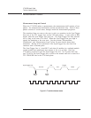
Sync/Trigger Line
Start of
State
End of
State
Pre-arm
Idle
Arm
Trigger
Meas
Figure 4-3: Transitions between states